A 5/8 WAVE GROUND-MOUNTED VERTICAL FOR 20 METRES
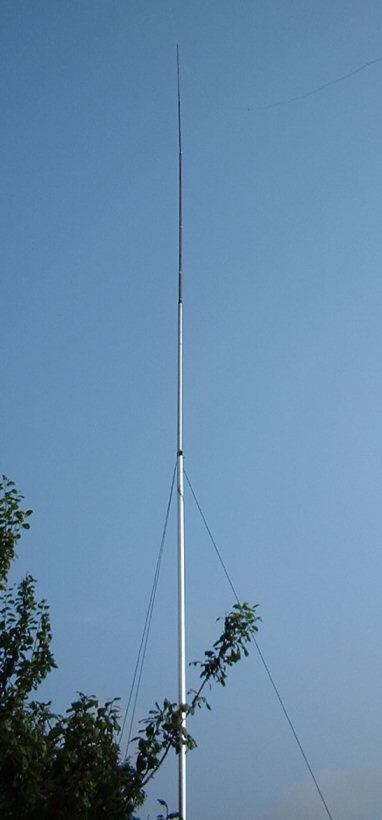
This is the big brother of the quarter wave vertical I described on another page. This vertical aerial is forty feet long. The bottom section is a twenty-foot, two inch diameter aluminium tube. Sticking out of the top of the tube is a seven foot length of one and a half inch diameter tube. Then, there’s thirteen feet of fibreglass rod with a wire running up it. The forty-foot pole supports my inverted L, that’s why the top of the fibreglass rod is bending over slightly. The three nylon guy ropes are twenty feet up the pole, giving enough support even in high winds.
This aerial is supposed to have some gain over a quarter wave ground-mounted vertical. I think it does have a little gain. In fact, I’ve heard more USA stations using this aerial than I ever did on the quarter wave version. And I’m getting better reports from around the world. I’ve worked Costa Rica and other exotic places with no problems. The main advantage of the 5/8 wave aerial is that the current maximum is about twenty four feet up the pole – rather than on the ground as with the quarter wave version.
I don’t know what the feed impedance of the aerial is, but it loads beautifully with a simple L-match ATU. Obviously, the more radials you fan out from the base of the aerial the better, but I’ve only used six. Some of the radials are tacked along the fence about one foot above the ground, others are running on the ground in the bushes. There’s no need to bury the radials, which saves a lot of work. Having said that, you can bury them an inch or so below the surface if you wish.
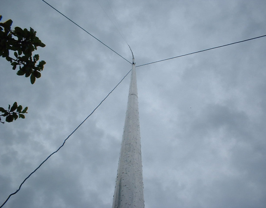
This picture was taken just after a major thunderstorm. Wow, just look at the way the pole climbs majestically up to the thundery clouds. Needless to say, the aerial wasn’t struck by lightning. That’s a plum tree at the top left of the pic. We have a few plums this year but the crop is disappointing. Perhaps the RF killed them off?
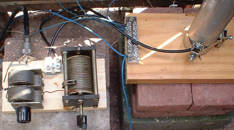
The ATU is normally covered with a plastic box to keep the rain out. I might even build a posh looking waterproof box one day. At the moment, I only have six radial wires. Each wire is sixteen feet long which is a quarter wave on twenty metres. The length of the radials isn’t that important, just lay out as many as you can. You’ll see from the above picture that the aerial is standing on a specially designed, military spec, insulated support assembly… a lump of wood. The ATU is standing on a pile of bricks. The connection to the base of the aerial is made by using earth clamps around the pole. The six blue wires connected to the terminal block at the base of the aerial are the radials going off in random directions.
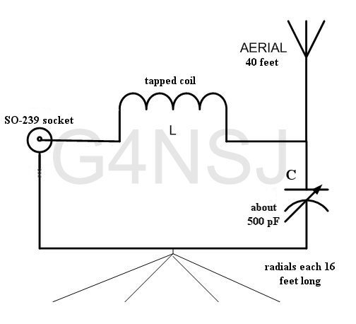
To load the aerial, turn the variable capacitor to its mid-way point and then tap the coil for the lowest SWR. Then, re-tune the capacitor for the lowest SWR. Repeat the process until the SWR is 1:1 I used an old roller coaster I found in the junk box, but you can wind a coil and tap it with a croc clip. By the way, tune the thing somewhere in the middle of the twenty metre band. The variable capacitor is physically small, but it doesn’t flash over when I stuff 100 Watts up it. If you want to run 10 kW then use a bigger capacitor. The ATU was a ten minute lash up!
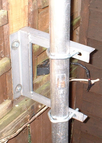
Ignore the wires, they are for something else. I’ll be wrapping some PTFE around the pole at some stage to insulate it from the bracket. Not that I think it’s necessary because the wooden fence is an insulator, but it will look good. I have a roll of some really thick PTFE which is about one foot wide and several yards long. The problem is… I can’t find it!
 CURRENT DISTRIBUTION ALONG THE AERIAL
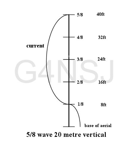
Ignoring the bottom 8ft section for a minute, you’ll see that the current is distributed over the half wave section of the aerial. This is exactly the same as the current distribution in a half wave dipole. This puts the current maximum at a good height up the pole – about twenty-four feet. With the bottom section included, the feed point impedance is easily matched by the simple ATU.
 THE VERTICAL AGAINST A BLUE SKY
This is a good aerial for twenty metres and it will bring you some pretty good DX. The radiation angle is low, the thing loads easily, and the bandwidth is incredibly wide. By the way, if you have a handy tree in the back garden, you can substitute the aluminium pole for a piece of wire. Just hang a forty foot length of wire down from the tree to the ATU and you’re on the air.
It all sounds so simple, doesn’t it? In reality, it is simple. What puts people off building their own aerials and ATUs is the fear of mathematics and the like. Yes, you can buy all sorts of aerials, but at an incredible cost. Take the very simple G5RV. So many people buy this aerial. Why not make one?
Make an effort and build the aerial described here and give it a try. You’ll be pleasantly surprised, I’m sure.
I found a company on the internet selling more or less the same aerial for $300. And that’s just the pole with no ATU, mounting bracket or anything else. Who needs to spend hundreds of pounds on a manufactured vertical? Besides, it’s more fun building your own aerials.
There’s a funny story about the radials I installed. Behind the fence by the aerial, there’s an alley way. I chucked some radials along the alley and pushed the wires into the weeds to hide them. Great stuff. But, within a couple of hours, along came our friendly gardener with his petrol-driven strimmer. He did a wonderful job of tearing the weeds to pieces. As for my radials… Hmm!
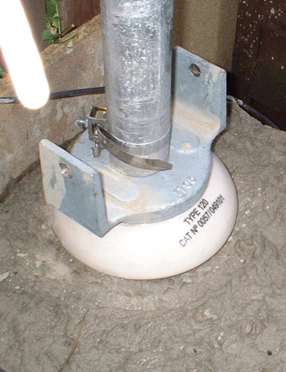
At long last, I’ve managed to get hold of an insulator (borrowed from the railway) for the base of the aerial. The insulator was designed to support the third rail, the conductor rail, and it’s ideal for my vertical aerial.
The photo shows the insulator embedded in concrete. The base of the pole is resting on the insulator at the moment but I will be drilling holes and sliding a huge bolt through the metal flanges and the pole to make a hinge type arrangement. This way, I will be able to lower the pole to the horizontal position without removing it from the base.
VERTICAL ANTENNA BASE MOUNT
Here you can see the holes drilled in the two flanges. The pole will be raised and a hole drilled through it for the long bolt. Ideally, I will need a piece of sleeving to go through the hole in the pole, but that all depends on what I can find in the junk box.