Audio introduction 25th October 23:
Update 1st November 23:
I’ll be adding to this page as and when I discover more about the transmitter.
Do pop back now and then to check for updates.
This is a lovely piece of kit. It’s American made and uses two 1625 valves in the PA. Covering 5.3 to 7MHz, I’m sure I can get it working on the 40 metre amateur band. There’s also the 5MHz AM frequency 5317kHz which the transmitter already covers. Once I’ve worked out the octal socket PSU connections, I’ll fire it up. It’s manufactured for The Navy Department – Bureau Of Ships. Model number CCT-52210. Why the bureau of ships, I have no idea!
The 1625 valve is an 807 variant with a 12.6 V heater and a 7-pin base. The 807 has a 6.3 volt heater.
Update 23/10/23:
I’ve worked out the valve heater connections to the octal PSU socket on the rear of the chassis. Although the label on the cabinet says 28 Volts, the heaters are wired for a 12 Volt supply. Each valve heater has the correct voltage and all valves glowing nicely. The next job is to work out the HT connections on the octal socket.
A mystery:
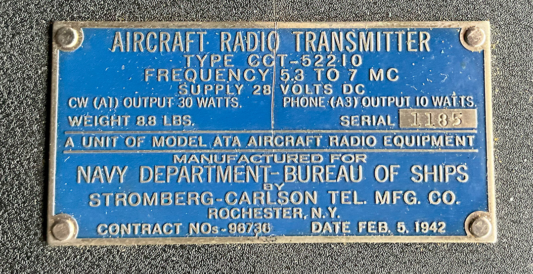
The information on the info plate seems to be incorrect, see photo below. AM 10 Watts. CW 30 Watts. I reckon that 30 Watts carrier out of a pair of 1625 valves seems rather low. There’s no socket for a Morse key. It would appear that the coax socket on the front panel is for a microphone. The label also states the supply should be 28 Volts DC. The valve heaters are wired for 12 Volts. What about HT? There’s no built in rotary converter or vibrator pack. The plate also shows a date, 5the February 1942. The HT smoothing capacitors, which appear to be original, are stamped April 1965. The plate states the frequency coverage is 5.3 to 7 MHz. Is that correct?
The information plate is totally wrong. For a start, the TX is SSB, not AM, as I initially thought.
I know very little about this transmitter so I’m open to all ideas. If you have any info on the TX, please let me know. [email protected]
Update 25/10/23:
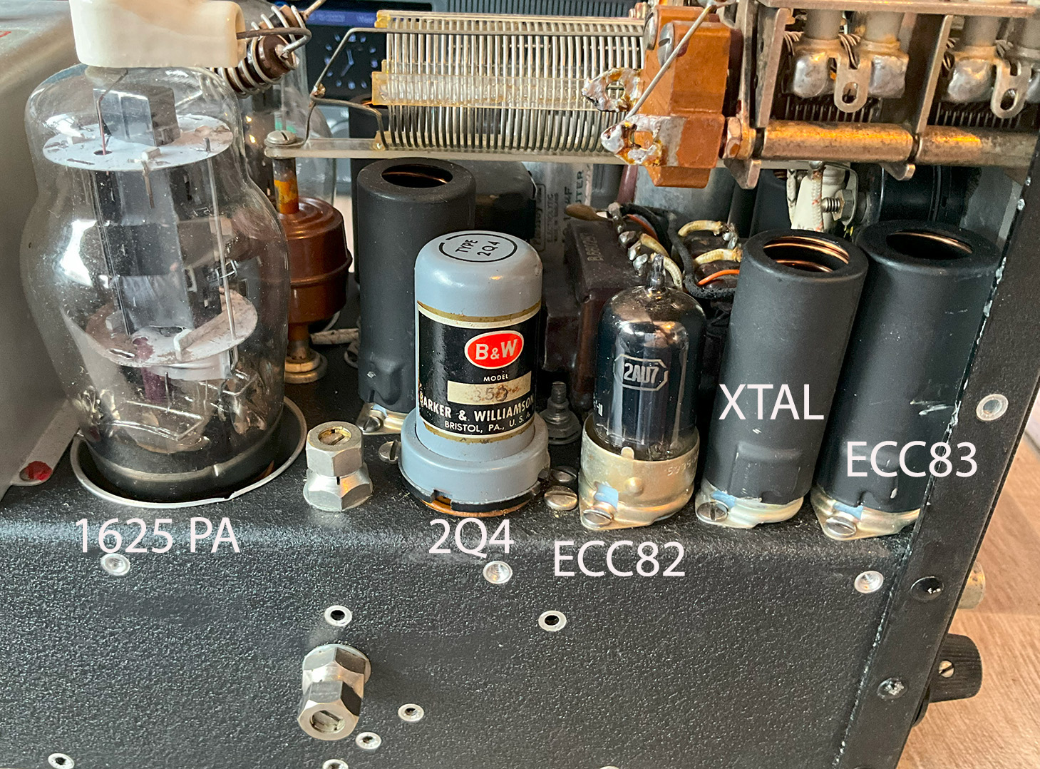
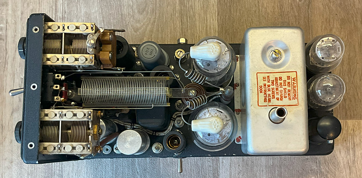
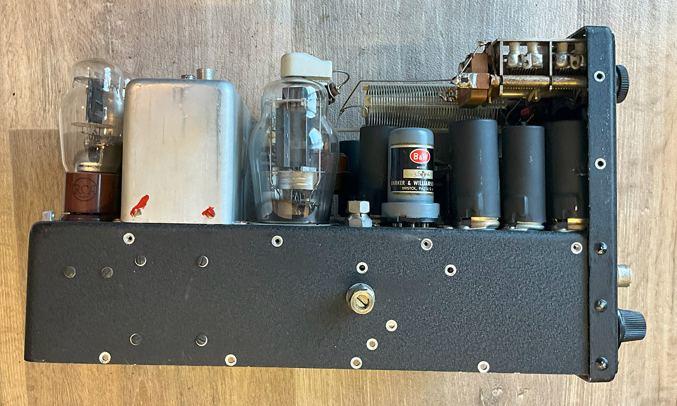
John contacted me and suggested that this is a conversion on an old WWII ARC-5 into a phasing SSB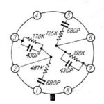 exciter/transmitter. I have looked into this and he is right! Here’s what I’ve discovered. The 90 degree phase shift over the audio range requires very precise values of resistors and capacitors in the network, see photo. Consequently, manufacturers produced phase shift networks, PSNs, as plug-in components. The most common was the B&W 2Q4/350 made by Barker and Williamson. These units were housed in a metal tube with an octal base and gave a 90 degree phase shift over the audio range of 300 to 3000 Hz. You can see the plug-in octal unit in the photo below. So this is an SSB transmitter and not, as I initially thought, AM.
Articles on the ATA and ARA aircraft equipment:
These articles don’t cover my transmitter but they are of interest. Thanks to Allen for the PDFs.
View the instruction book here.
View the article here.
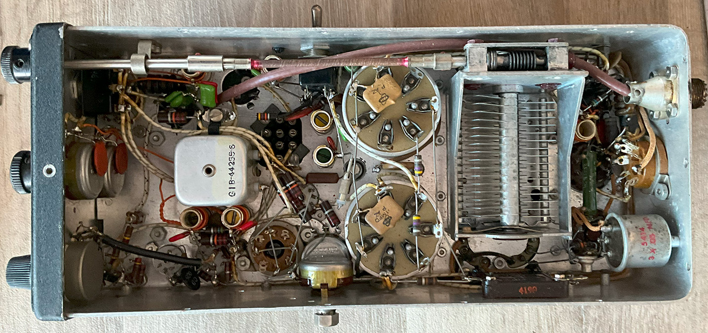
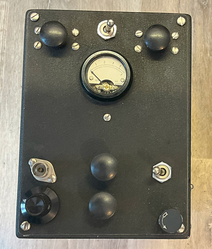
Shown below are photos of the transmitter. Click on the photos for a larger images. And there’s a video at the bottom of the page.
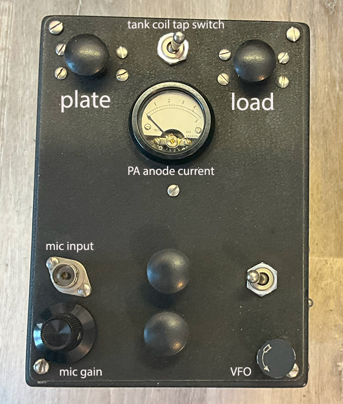
The meter:
Pin 4 on the PSU octal socket on the rear of the chassis is HT for the 1625 PA valves, probably 500 or 600 Volts. The supply goes to the meter, which reads current, and then to the PA valve anodes via an RF choke. The meter is calibrated 0 – 5 which might be 0 to 500mA.
The octal PSU socket:
Pin 1 – To 6BA6 valve. I can’t see to which pin as the valve base is completely obscured by a toggle switch.
Pin 2 – Heaters 12 Volts.
Pin 3 – NC.
Pin 4 – HT for the 1625 PA valves, probably 500 or 600 Volts.
Pin 5 – NC.
Pin 6 – Low HT for all other valves, probably 250 Volts.
Pin 7 – To pin 4 of VR150. I’m not sure why, as yet.
Pin 8 – Ground.
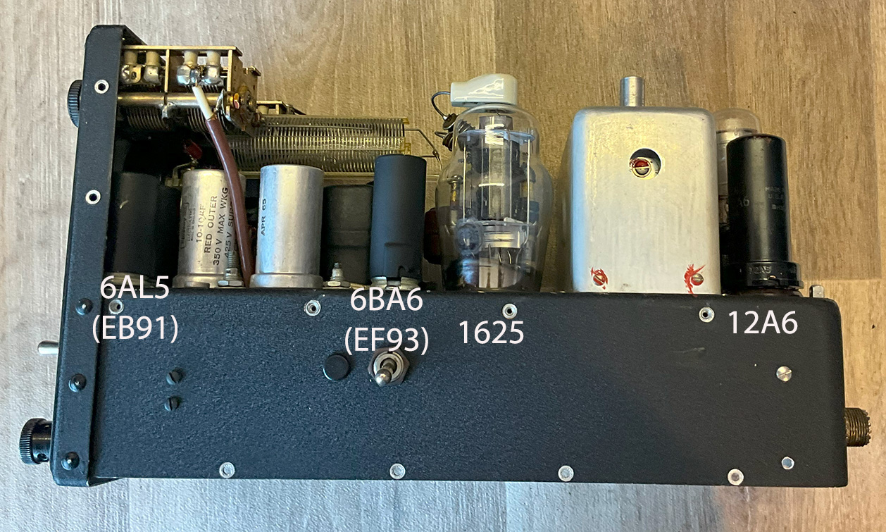
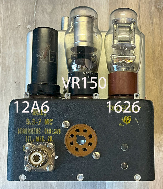
The valves:
1625 – RF PA.
12A6 – Was designed for use in the single ended audio output.
VR150 – HT voltage stabiliser.
ECC83 – Double triode.
ECC82 – Double triode.
1626 – Was designed as an RF power oscillator.
6AL5 – Double signal diode.
6BA6 -A variable μ pentode for use at HF.
More to follow as and when I can get to the valves.
NanoVNA check on the Xtal and VFO frequencies:
Using my NanoVNA, I’ve checked the xtal and VFO frequencies. The xtal is marked 9061.11kHz. On the NanoVNA, I get a reading of 9.06MHz, so I’m not that far out. According to the NanoVNA, the VFO covers 5.14MHz to 6.85MHz. According to the info plate, the transmitter is supposed to cover 5.3 to 7MHz.
How it works: (How I think it works!):
As I understand it so far. Please correct me if I’m wrong. A crystal oscillator is used to generate a stable RF carrier. To generate the modulating signals, additional circuitry is required to modulate the crystal oscillator’s output. This can be achieved through methods like amplitude modulation or frequency modulation of the crystal oscillator signal.
Once modulation is applied, the resulting signal will contain both upper and lower sidebands. To create SSB, additional circuitry is required to select either the Upper or Lower Sideband and suppress the unwanted sideband. This involves phase-shifting and filtering.
The VFO output is mixed with the output of the crystal oscillator. This mixing process involves creating in-phase and quadrature components and modulating them onto the carrier signal, as is done in the SSB modulation process.
Using a crystal oscillator to generate modulating signals is less common than using a VFO because it limits the flexibility to change the modulation frequency. VFOs are designed for this purpose and provide easy tuning and adjustment of the modulation frequency, making them more versatile for applications where the modulation frequency needs to change frequently, such as voice or data communication.
In contrast, crystal oscillators are prized for their stability and accuracy, making them well-suited for generating a stable carrier frequency. However, when used for modulation, they may require additional components and more complex circuitry to achieve SSB or other modulation schemes.
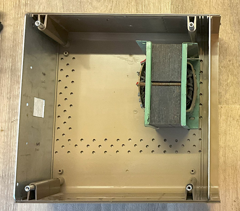
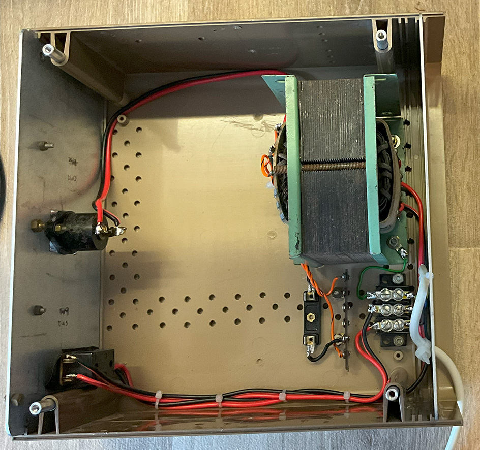
The power supply:
For those who might be interested, I’ll be uploading information and photos of the power supply construction. So far, I’ve found a suitable box and a transformer for the 250V HT supply. The HT winding is centre tapped so a couple of 1N4006 diodes will allow full wave rectification. Mains on-off switch fitted, indicator light on front panel, mains lead connected, HT fuse holder in place… I’ll replace the aluminium back panel at some stage as it’s full of holes.
Big problem:
The transformer HT winding is 250 volts. Once bridge rectified and smoothed, the DC voltage is approximately 350. Far too high!
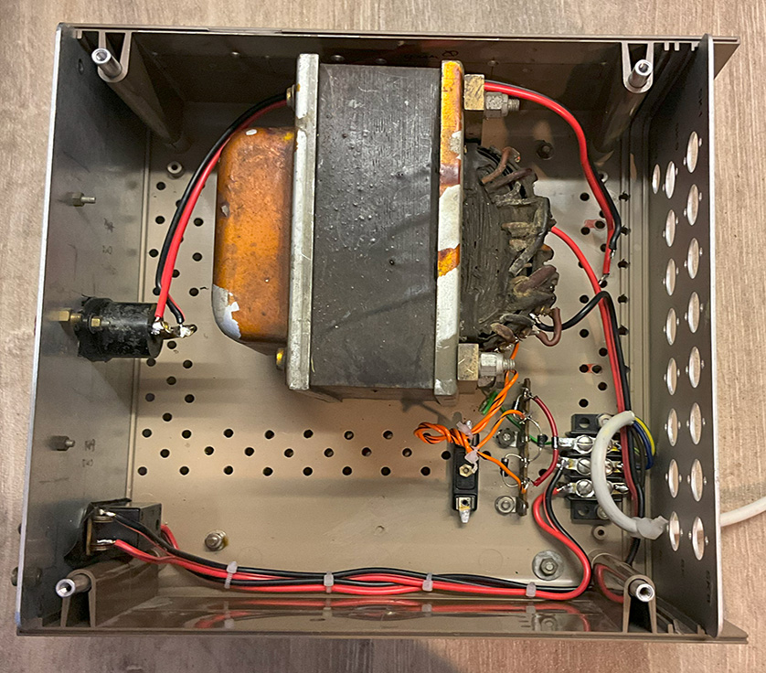
Major update:
I’ve now found a far better transformer, see photo on the right. This one has two 6.3 volt windings at a few amps, ideal for the 12 volt heaters. It also has a 185 volt HT winding, which should give around 250 volts when rectified and smoothed. There’s another HT winding, 345-0-345. That will equate to just under 500 volts DC. Ideal for the PA anodes.
Update 31/10/23:
I’ve connected the 250 volt output from the PSU to the TX, the crystal oscillator and VFO are both running. I poked a finger into the mic socket, the buzz from the audio amplifier modulates the 9061kHz signal from the crystal oscillator. On a receiver, I can hear carriers from the xtal oscillator, 9061kHz, and the VFO, 5 to 7MHz. I’ve not heard a SSB signal yet. I won’t be connecting the higher HT voltage for the PA anodes until I’m happy with all other stages of the transmitter.
Update 1/11/23:
With a dummy load connected to the aerial socket, I’ve put a couple of hundred volts on the PA anodes. The PA anode current meter on the front panel doesn’t move but, the S meter on my receiver does vary as I adjust the Pi network capacitors. Still no SSB detected on the receiver.
Update 2/11/23:
Here is a link to here original QST article. This includes the circuit diagram.
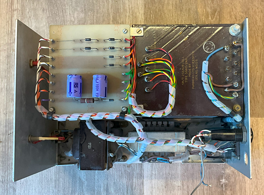
Update 9/11/23:
Thanks to Rod G3YHM for giving me this lovely homebrew power supply, see below. It supplies negative bias, 12 volt heaters, 600V HT and 250V HT. There’s a fuse holder missing but that’s not a problem. I shall use this one rather than try to find suitable parts for the one I’m building. Nice job, Rod. Well done! At the moment, I’m running the PSU on half mains voltage for a few hours so as to not terrify the smmoothing caps with high voltage.
Thanks to Dave for the info below…
HF SSB aircraft bands
| Frequency Range | Civililian sub band – Military sub band |
| 2850 kHz to 3155 kHz | 2850 – 3025 kHz civilian – 3025 – 3155 kHz military |
| 3400 kHz to 3500 kHz | 3400 – 3500 kHz civilian |
| 3800 kHz to 3950 kHz | 3800 – 3950 kHz civilian |
| 4650 kHz to 4750 kHz | 4650 – 4700 kHz civilian – 4700 – 4750 kHz military |
| 5450 kHz to 5730 kHz | 5450 – 5680 kHz civilian – 5680 – 5730 kHz military |
| 6525 kHz to 6765 kHz | 6525 – 6685 kHz civilian – 6685 – 6765 kHz military |
| 8815 kHz to 9040 kHz | 8815 – 8965 kHz civilian – 8965 – 9040 kHz military |
| 10005 kHz to 10100 kH | 10005 – 10100 kHz civilian |
| 11175 kHz to 11400 kH | 11175 – 11275 military – 11275 – 11400 kHz military |
| 13200 kHz to 13360 kH | 13200 – 13260 civilian – 13260 – 13360 kHz military |
| 15010 kHz to 15100 kH | 15010 – 15100 kHz military |
| 17900 kHz to 18030 kHz | 17900 – 17970 civilian – 17970 – 18030 kHz military |
| 21870 kHz to 22000 kHz | 21870 – 22000 kHz civilian |
| 23200 kHz to 23350 kHz | 23200 – 23350 kHz civilian |