Correctly termed, the AMU is an aerial matching unit. It does NOT tune the aerial.
The term ATU has become extremely popular over the years. But this device is not an aerial tuning unit. It does not tune the aerial. It’s a matching device, matching one impedance to another. Hence, aerial matching unit or AMU. The output impedance of most amateur transmitters is fifty ohms. The impedance of an end-fed wire could be anything between twenty and several thousand ohms. If the impedance of your end-fed aerial is two-thousand ohms, it doesn’t change. The matching unit doesn’t miraculously change the aerial feed impedance to fifty ohms. Neither does it change the fifty ohm output impedance of the radio to two-thousand ohms.
The AMU transforms the impedance from two-thousand ohms to fifty ohms. In other words: two-thousand ohms in, and fifty ohms out. A mains transformer transforms 240 volts to, say, 12volts. It doesn’t somehow alter the mains supply voltage. That remains at 240 volts no matter what you do. Remember, an AMU does NOT improve the performance of an aerial. A poor aerial is a poor aerial, no matter what you do at the feed point. Frightening stuff? Not really. What is frightening is the misconception, the myths, surrounding this impedance matching device.
Link coupled tuners:
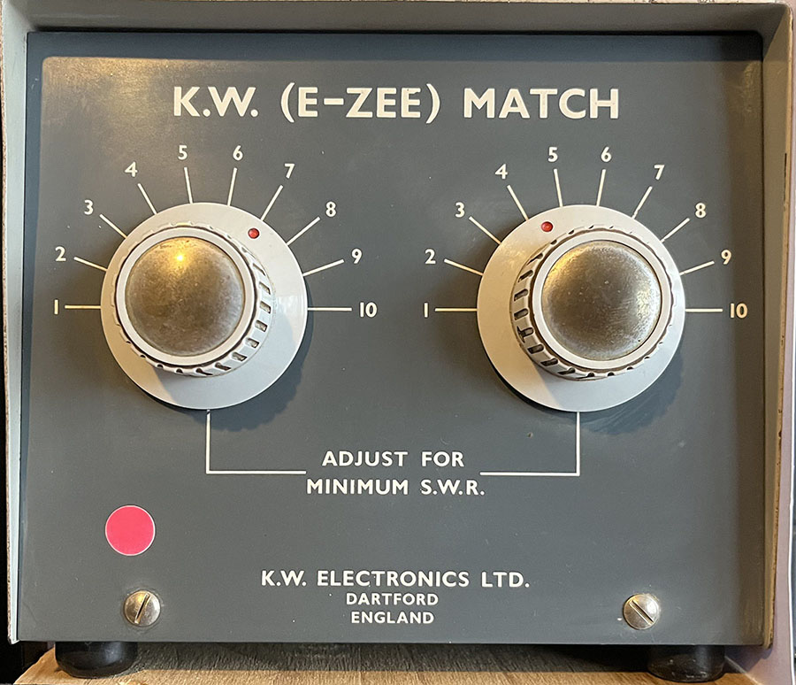
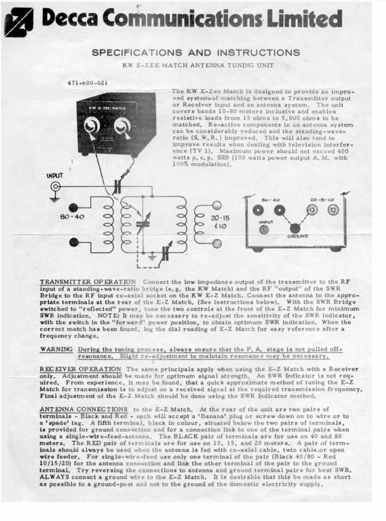
Link coupled tuners, such as the KW-E-Zee Match, shown below, have advantages over other types. Excellent balance and low loss, for starters. Also, they exhibit bandpass functionality, enhancing transmission and preselection for the receiver. You’ll notice that there is no band switch on the KW-E-Zee Match. This reduces complexity, enables a more compact design, avoids losses and maintains symmetry throughout the tuner. The disadvantage is that you have to move the openwire feeder back and forth when switching from high bands to low.
Unbalanced tuners disguised as balanced:
Many tuners on the market are sold as ‘balanced’ or ‘symmetrical’ when, in fact, they are unbalanced or asymmetrical. In other words, an L match or T match tuner with a balun stuck on the end is NOT a balanced tuner. The KW-E-Zee Match link-coupled tuner is balanced, as are the KW-107 and the SEM TranZmatch link-coupled tuners. A tuner using a balan to couple to a balanced line is an unbalanced tuner with a balun. By the way, if you are going to use a balun it should be a current type, not a voltage type.
 KW-E-Zee Match:
I bought a KW-E-Zee Match ATU recently. It’s used, but in pretty good condition. I used to own a KW-107 ATU but I sold it. It was big and clunky, taking up a huge space in my shack, and I didn’t really like it. Having said that, it was a brilliant ATU.
Frequency Range 3.5 MHz – 30 MHz
Resistive Loads: 15 ohms – 5000 ohms
Maximum Power: 400 Watts SSB, 100 Watts AM.
There are two pairs of terminals on the rear panel. The black terminals are for the lower bands, 80, 60, 30 and 40. The red terminals are for the higher bands, 30, 20, 15, 12 and 10. The black terminal is the earth connection. There is no band switch, unlike the KW107. The balanced feeder has to be swapped between the terminals to change from low to high bands, but that’s not a problem. Also, as with other KW ATUs, there is no balun in the unit.
The ATU matches my doublet on all frequencies between 3 and 30MHZ. Excellent!
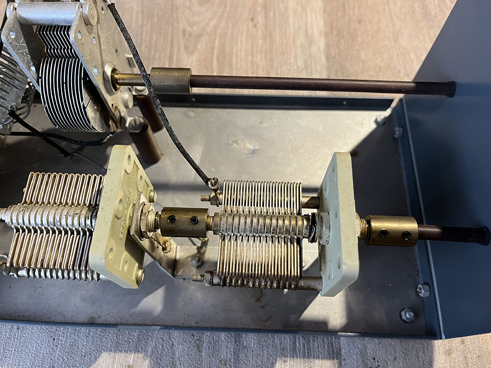
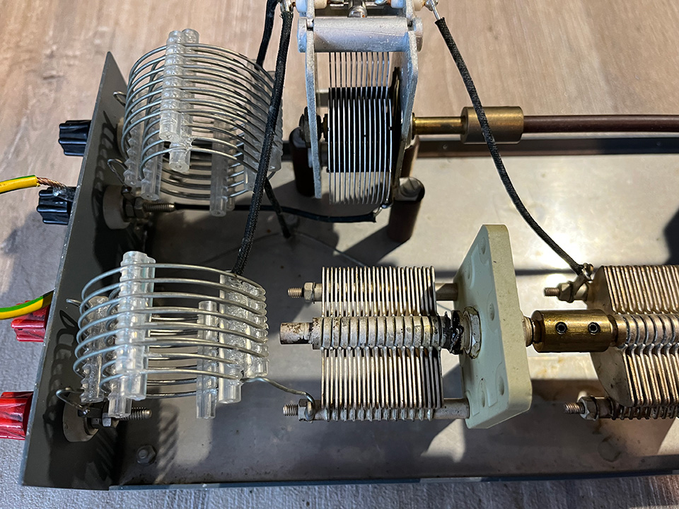
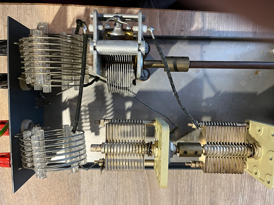
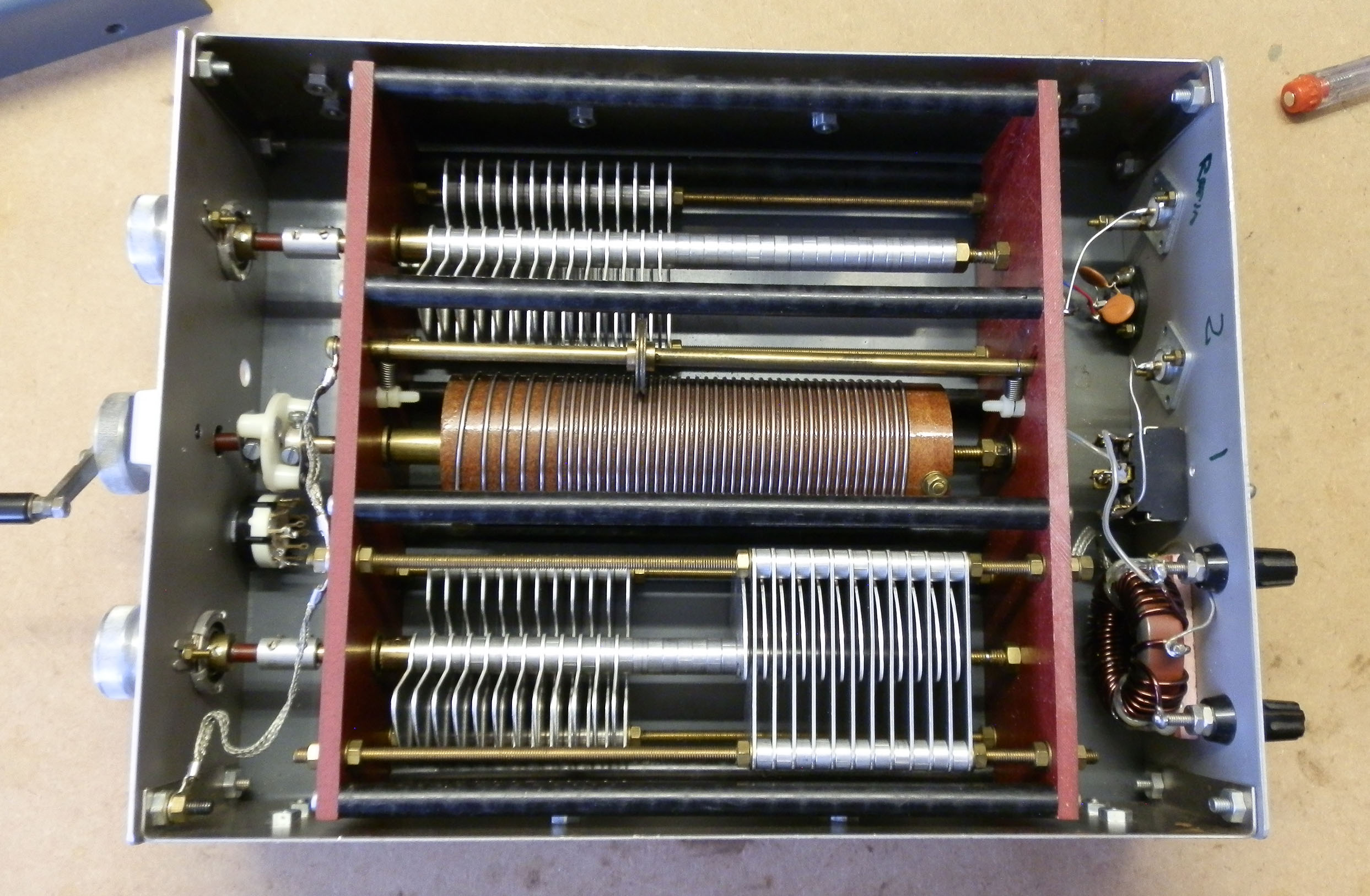
The photos below show the KW E-Zee match variable capacitors and coils.
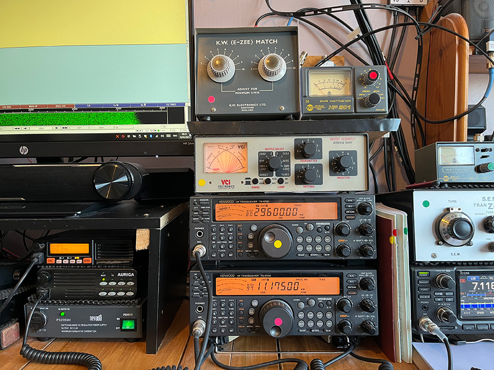
The photo below shows the KW E-Zee match installed with its SWR meter to the right. By the way, I ripped the guts out of the SWR meter and built my own design in the box. The original was designed for CB and wasn’t too good on top band. The coloured dots on the various units are to let me know which ATU and SWR meter are for which rig. I’m easily confused!
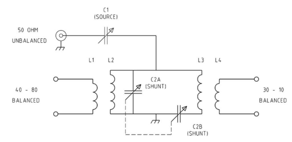
The KW E-Zee match circuit diagram:
The KW E-Zee match instruction leaflet:
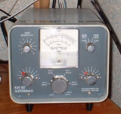
KW-107 Supermatch:
Below is my KW-107 Supermatch. After many years, I finally sold this one. The main reason was that is doesn’t cover top band. No doubt I’ll regret it but, hey ho! The instruction manual is here.
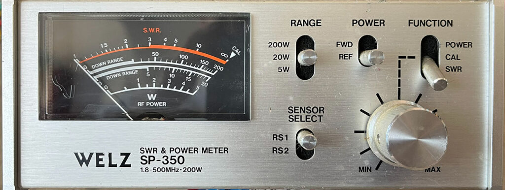
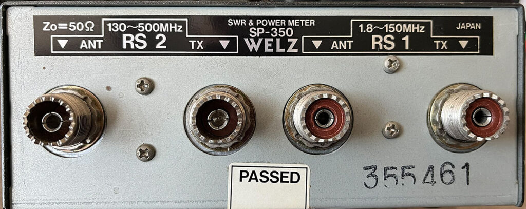
Welz SP-350 SWR and power meter:
Manufactured by Welz, Japan.
Range 5W, 20W, 200W.
1.8-500MHz.
Impedance: 50 Ohms.
Welz SP-350:
S.E.M Transmatch:
Below is my S.E.M Transmatch. I use this with my doublet and my Kenwood TS570D and my Icom IC-7300.
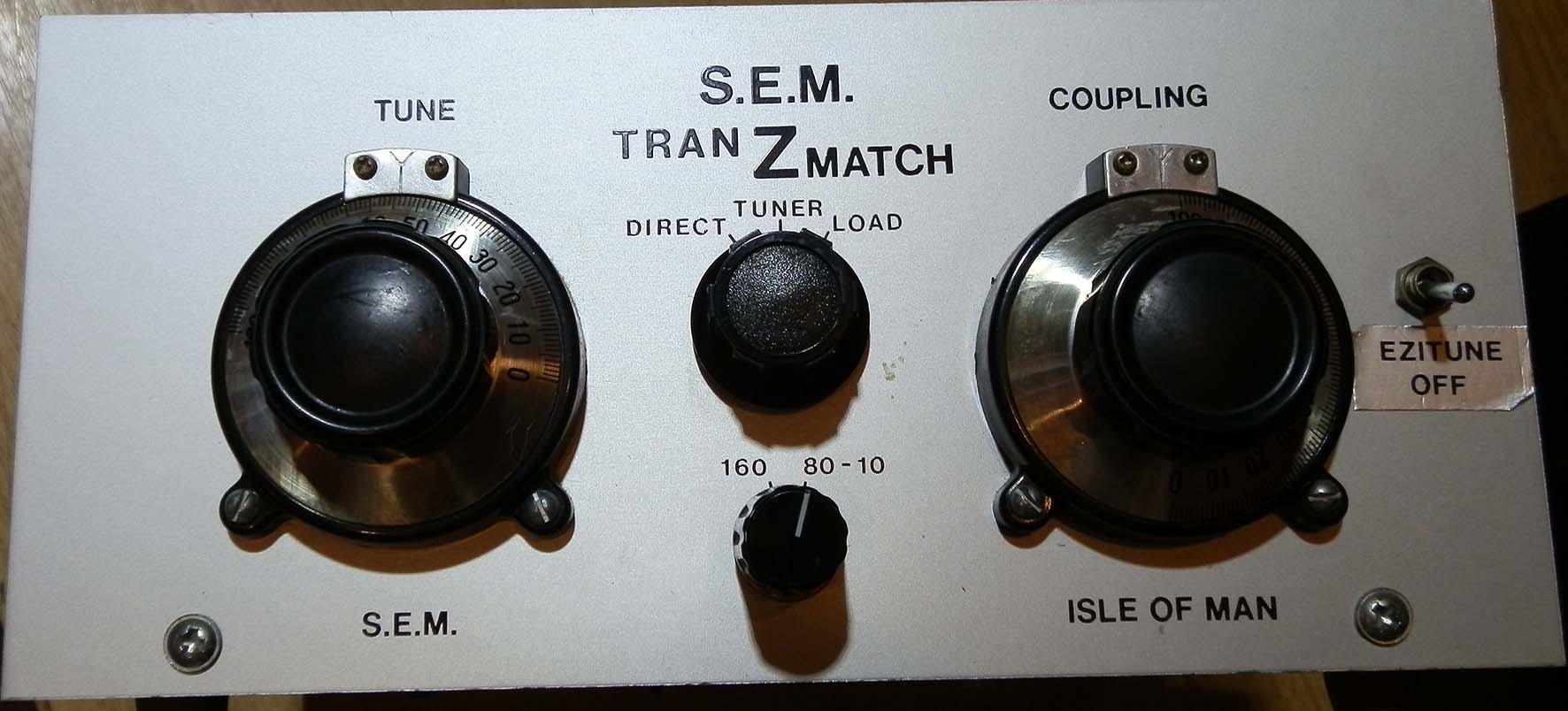
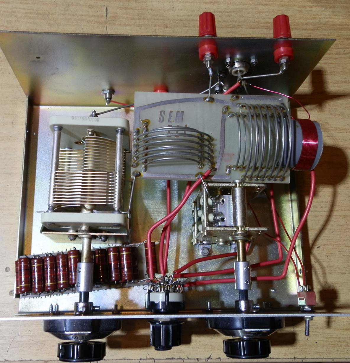
The photo below shows the inside of the SEM Tranzmatch. I don’t think much of the dummy load, it’s just a few 2 Watt resistors in parallel. I suppose it’s all right for low power but it’s pretty much a waste of space. I don’t think much of the Ezitune feature, either. It’s another unnecessary waste of space. However, it’s s great aerial matching unit and I’m very pleased with it.
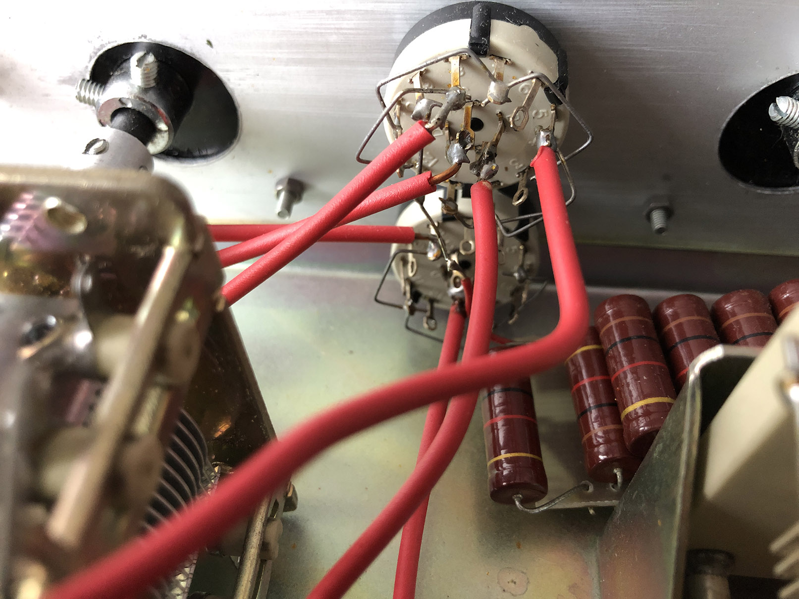
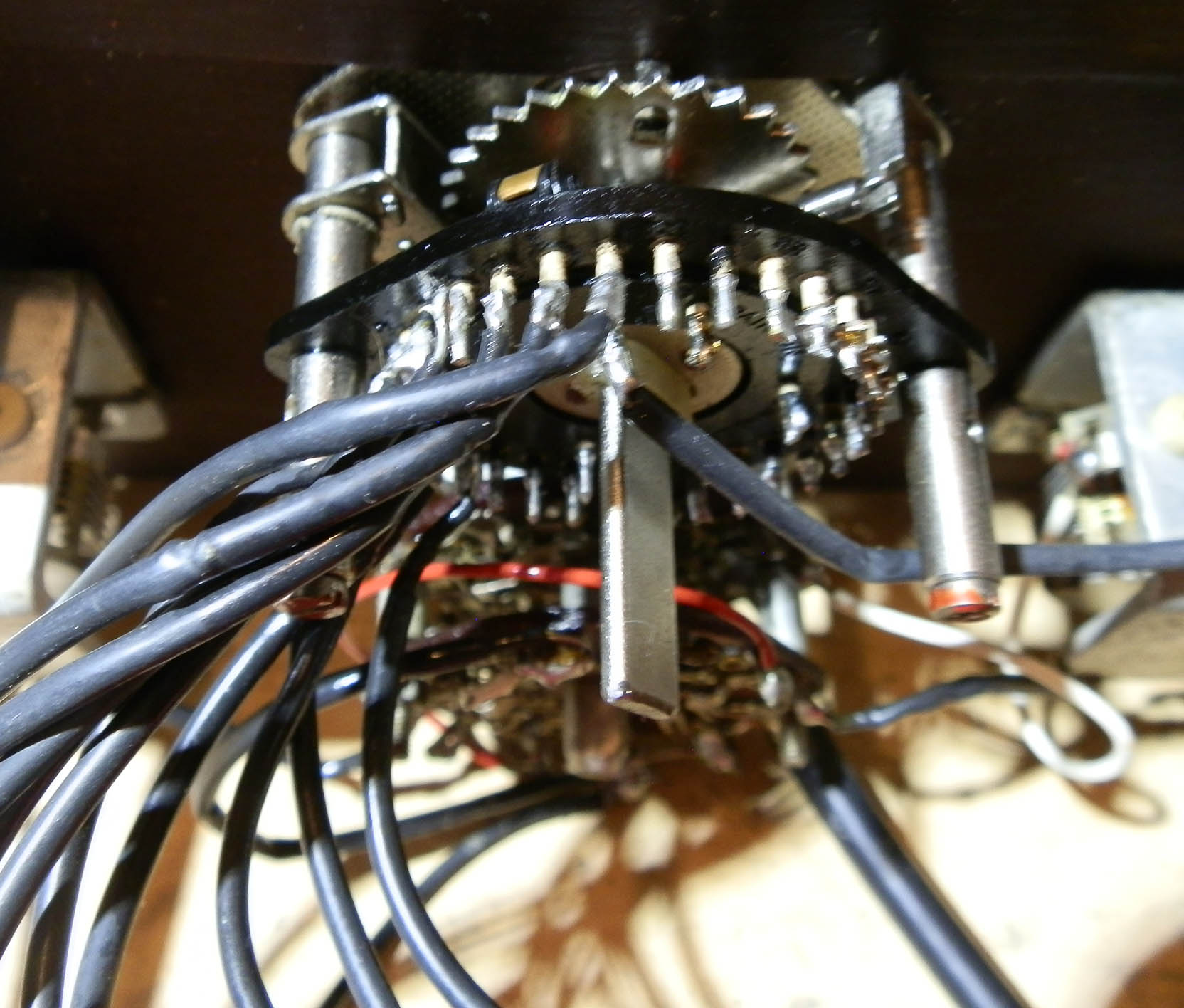
Several people have asked about the SEM switch wiring connections so these photos might help.

I’ve purchased another S.E.M Transmatch:
I’ve been very pleased with this tuner so, when I saw one for sale, I grabbed it. Info coming soon…
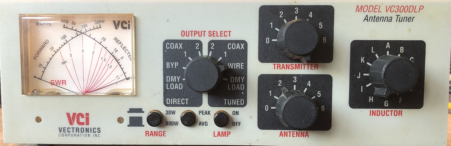
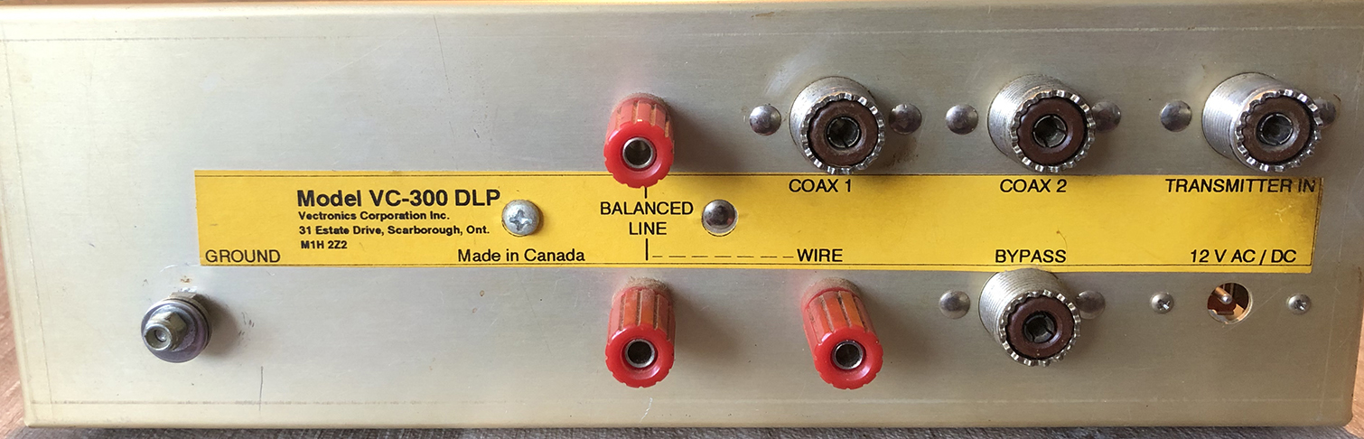
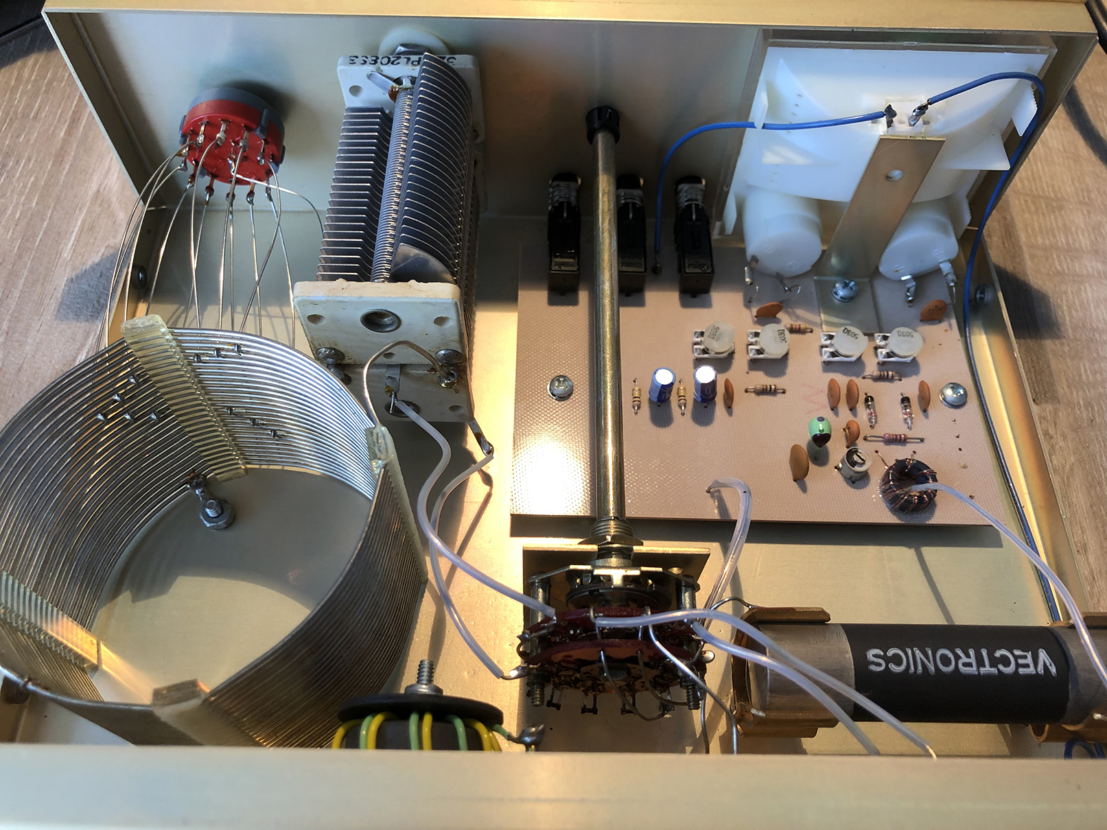
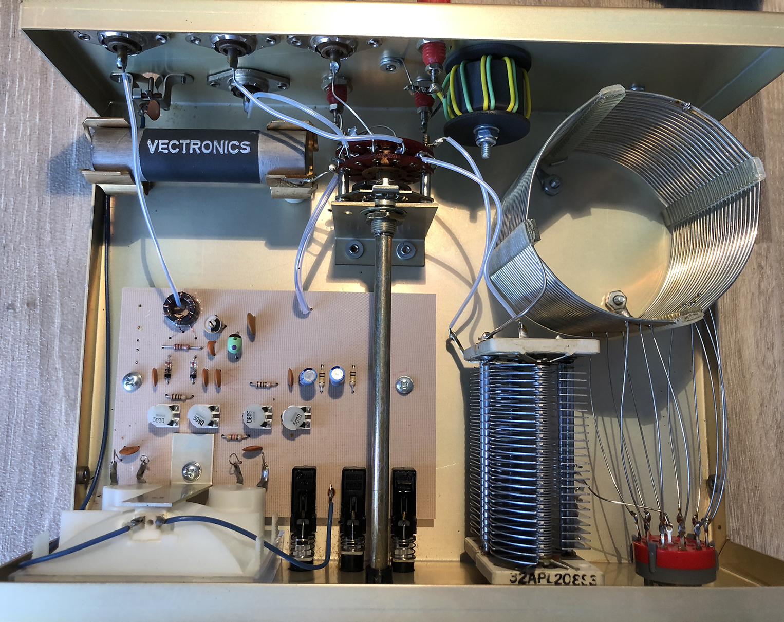
Vectronics VC-300DLP 1.8-30MHz ATU. 26-08-21:
This Canadian AMU is my latest acquisition. The user manual is here. I thought this ATU used a Pi network. However, a quick look at the manual reveals that it’s a T network. Very useful for matching aerials with low feed impedance.
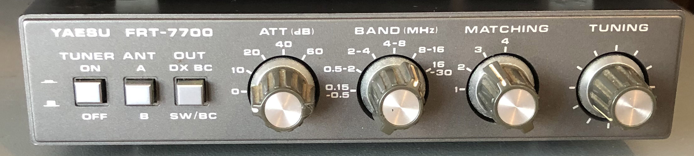
The Yaesu FRT-7700 ATU.
I’ve bought an FRT-7700 ATU to go with my Yaesu FRG7, see photo below. It’s made for the Yaesu FRG-7700 but, obviously, it will work with any receiver.
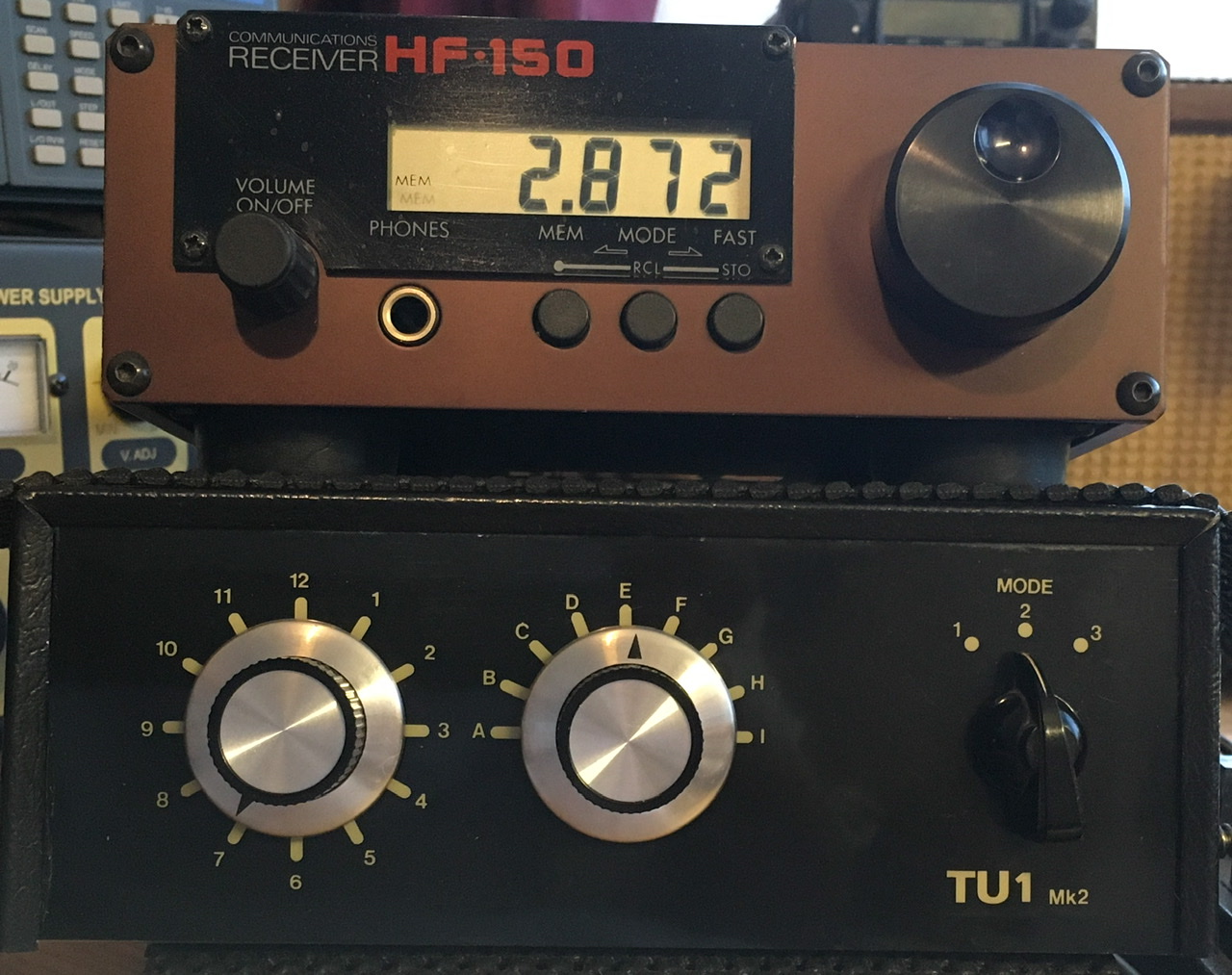
Lake Electronics TU1 MK2:
Shown below is my Lake Electronics TU1 MK2 aerial tuning unit, aerial matching unit, circa 1988. I use this with my Lower HF-150 communications receiver which has no front end selectivity. The matching unit helps with out of band second order intermodulation problems. The lower photo shows inside the matching unit. I’d really like to replace the horrible Belling Lee coax sockets with SO239 sockets but I don’t want to modify the unit.
.Shown below is the original L Match unit with Belling-Lee coax sockets and the so-called mode switch which, I believe, was wired incorrectly.
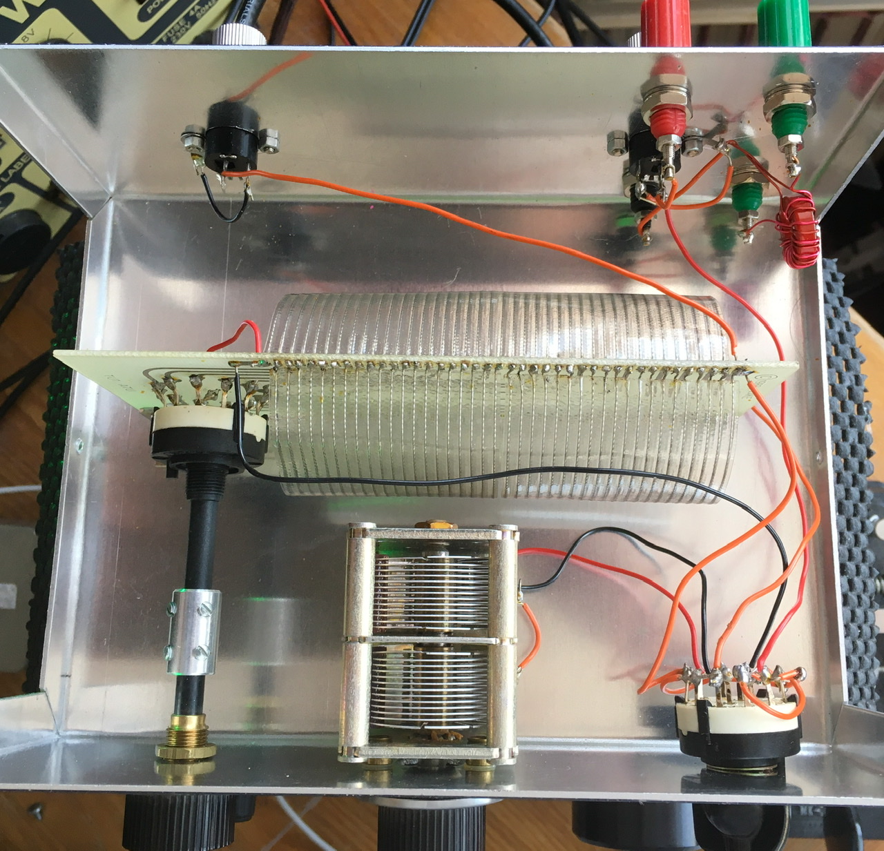
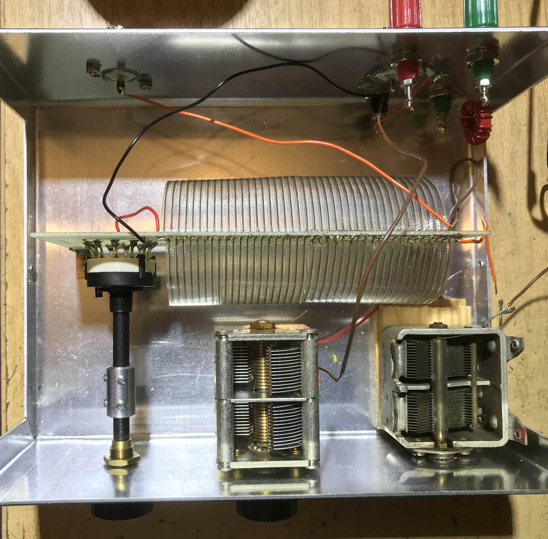
I couldn’t cope with intermittent coax sockets so I’ve fitted SO239 sockets instead. Also, I didn’t like the L-match circuit with a mode switch. I removed the rotary switch and fitted another variable capacitor to create a Pi network. See photo below. The unit can be returned to its original condition quite easily, which is important when modifying vintage gear.
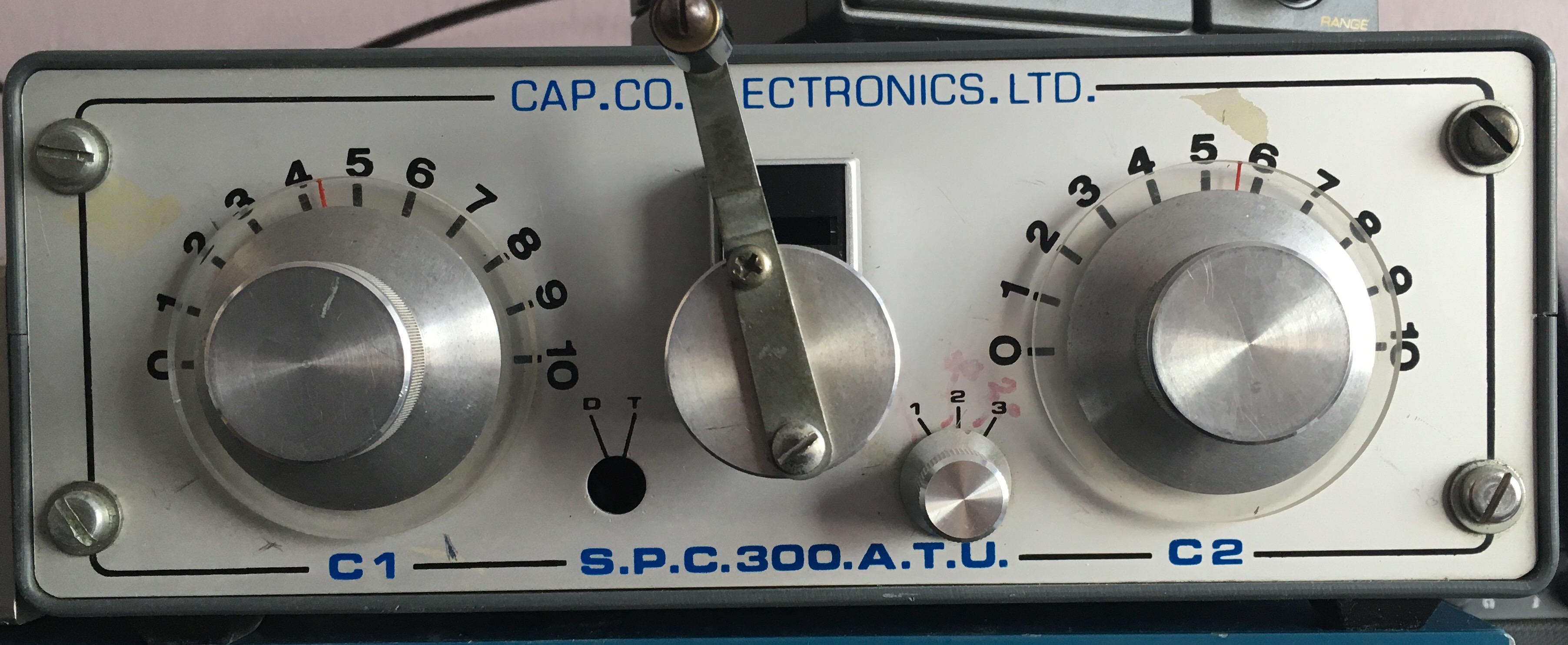
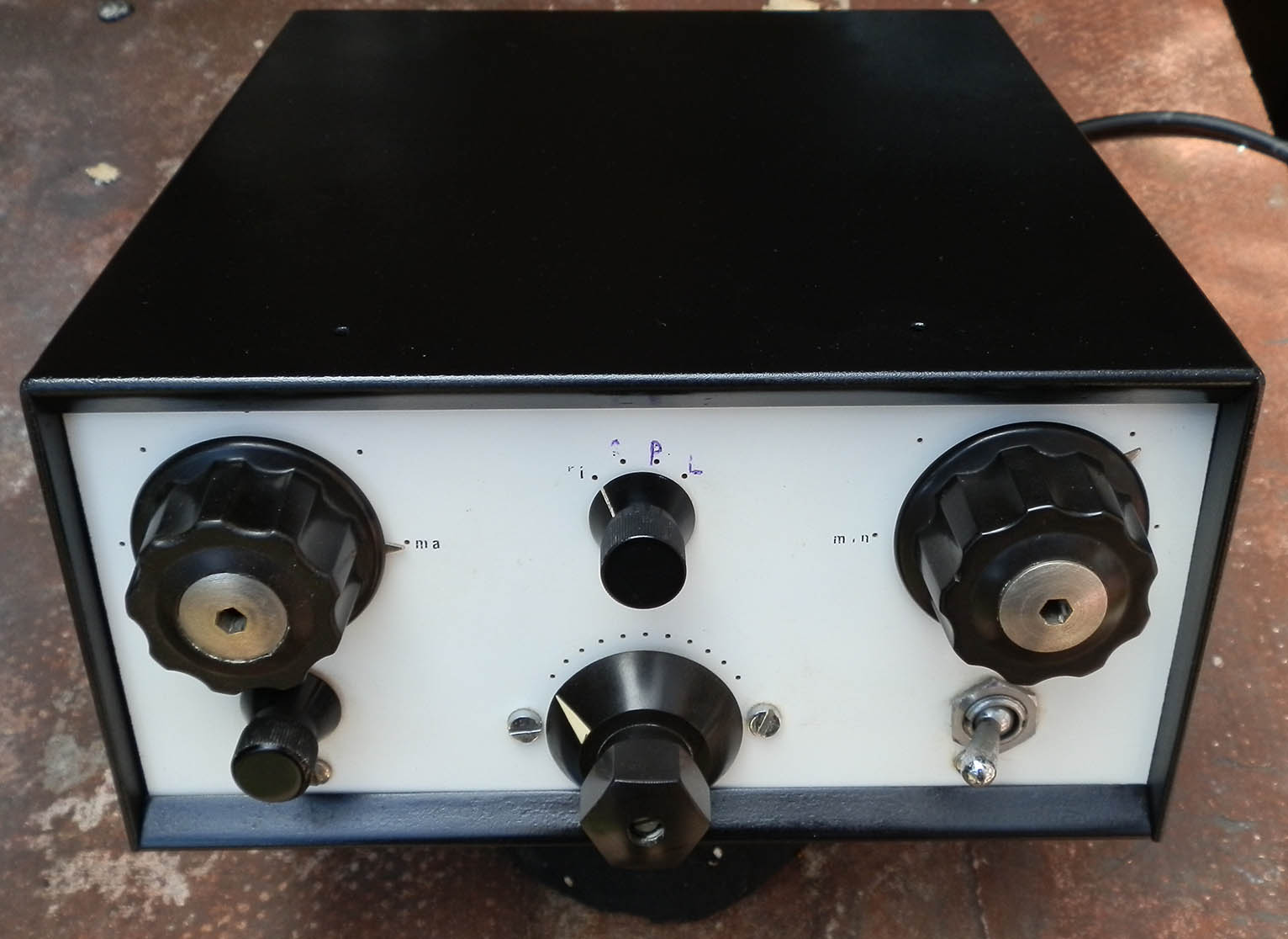
CAP.CO S.P.C.300 ATU:
Below is my CAP.CO S.P.C.300 ATU. This is brilliant! A lovely roller-coaster and two beautiful variable capacitors, this unit will match anything from 1 to 30MHz. I’ve also included a photo showing the inside of the unit. This is a fantastic AMU for using with a doublet.
Variometer:
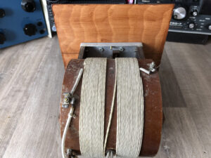
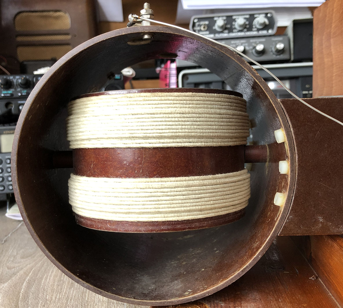
This is what’s known as a variometer, a rotating coil within a fixed coil. I think it was made by Marconi. I can’t remember where I got it from but I believe it was originally from a ship’s radio room. The outer coil is 6 inches diameter and the inner is 5 inches diameter. No doubt it would handle quite a few Watts. It’s perfect for matching an end-fed wire, even on medium wave! Not that I’ve tried it, of course. Better than medium wave, it was probably used for reactive loading of a 500kHz maritime antenna. I’m not surprised that it works so well on medium wave. The range, on my meter, is 143mH to 584mH.
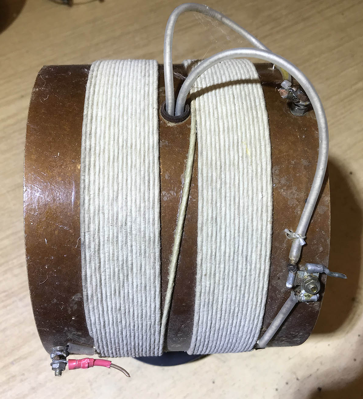
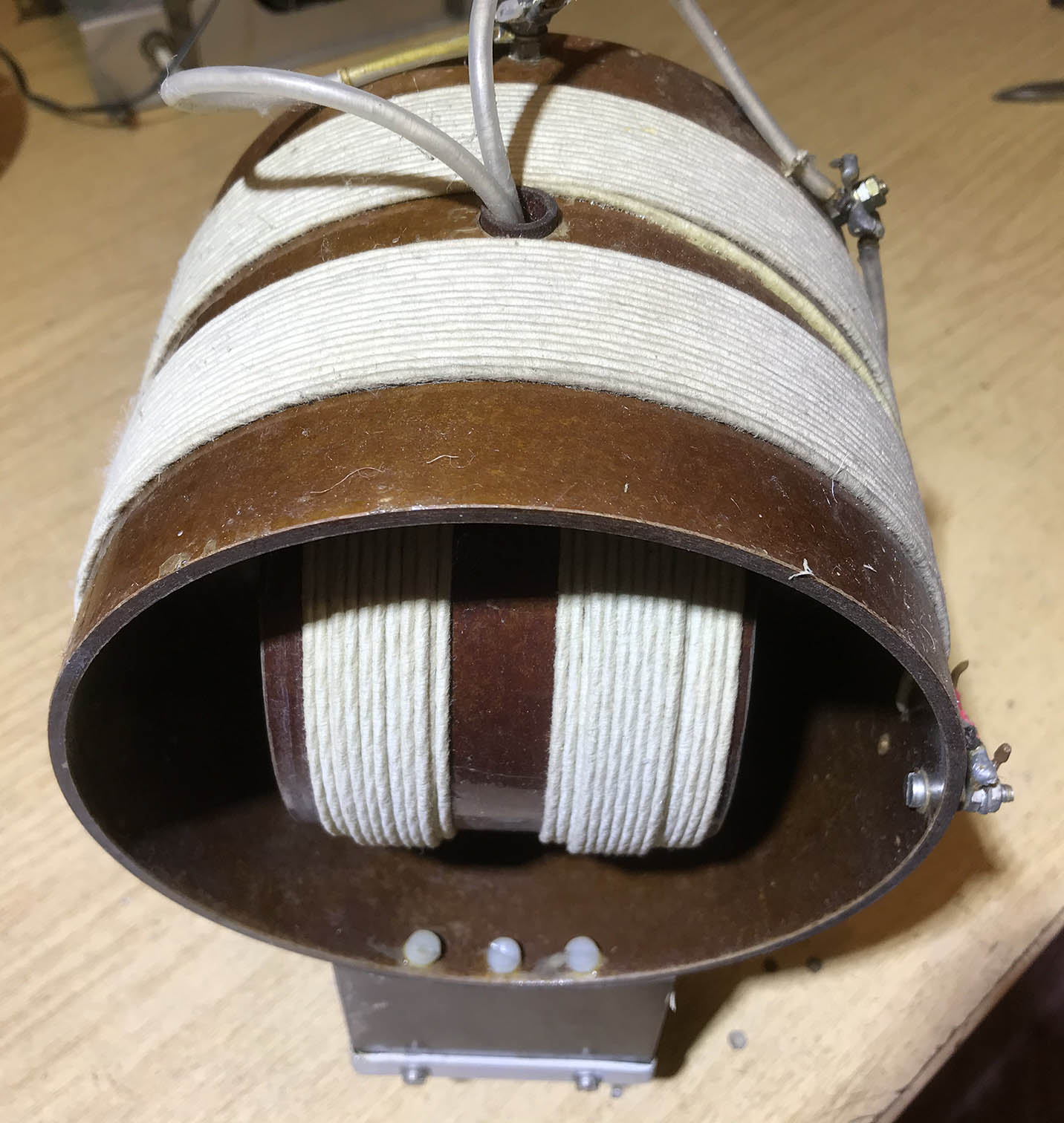
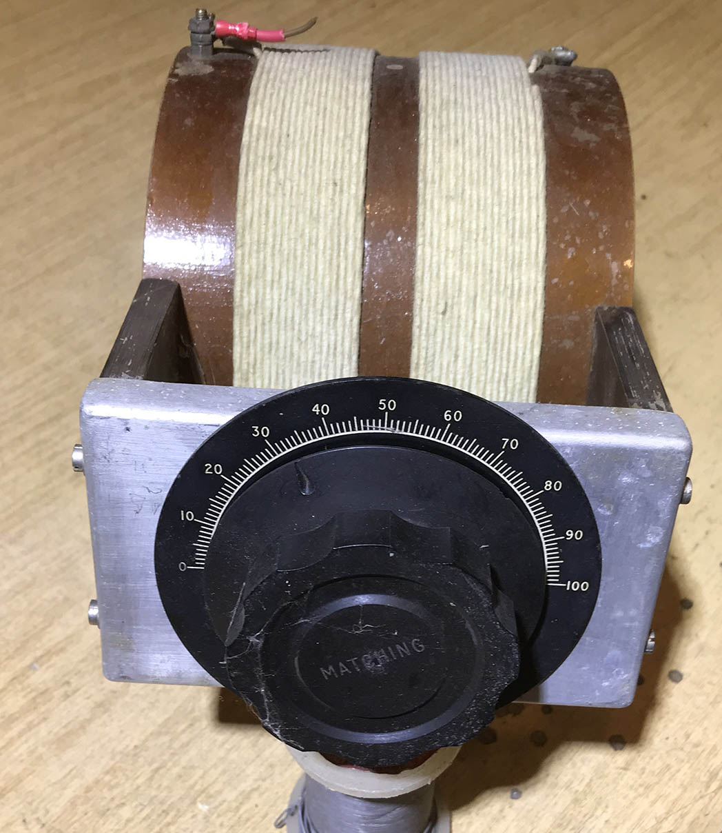
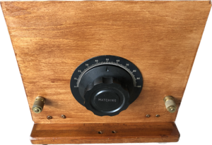
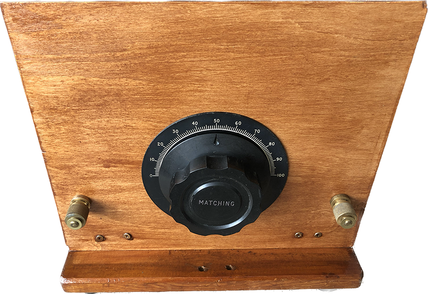
The photos below show the variometer mounted on a wooden frame. I found some old brass terminals, which look the part. I’ll probably mount an RF ammeter on the front panel for tuning purposes… tune for maximum smoke! This will be a useful unit to use with an end-fed wire. The first variometer I owned was one that came with a 19 set. It was great for short whip aerials, such as used on tanks and armoured vehicles. I have tried the variometer on various lengths of wire at different frequencies and it would appear to be limited. I have yet to try it on a 12 foot whip.
-
- Variometer

-

- Variometer
-
- Variometer antenna loading
Unknown ATU:
I bought this one, shown below, from a friend recently. Judging by the size of the variable capacitors, it’s obviously for low power TX or receive only. It will make a nice preselector for a comms receiver.
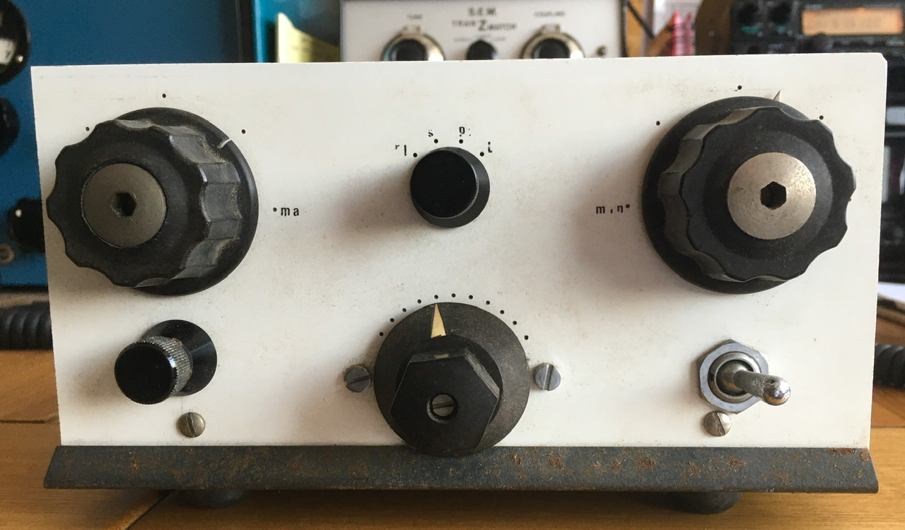
There are 11 taps on the coil and it would appear that the unit can be switched between various configurations. There’s no manufacturer’s name on the unit but I don’t think it’s home made. The steel case was rusty so I’ve rubbed it down with wet and dry and I’m in the process of spraying it black.
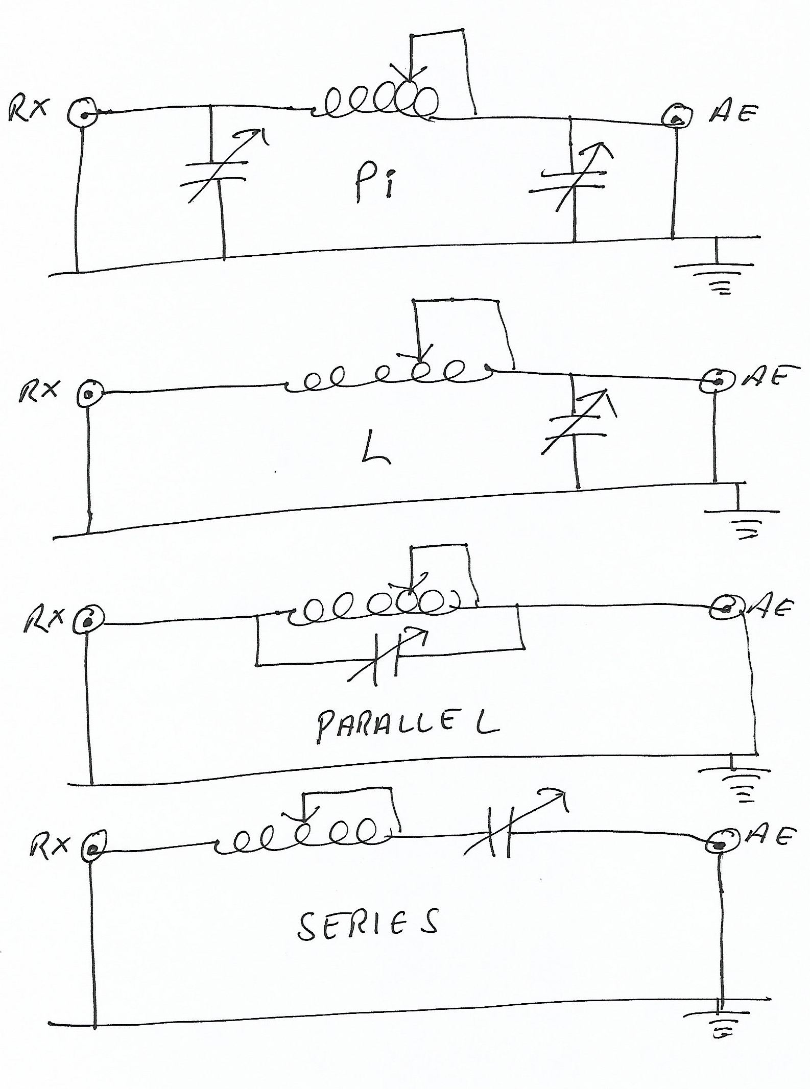
I spent over an hour tracing the wiring and drawing the circuit diagram, and I’ve discovered something rather interesting. See simplified circuit diagram above. There are four configurations and an off position. Pi Network. L Network. Parallel resonant tuned circuit in series with the aerial. Series resonant tuned circuit in series with the aerial. The parallel position will be useful for rejecting or blocking one particular frequency. For example, from a local transmitter.
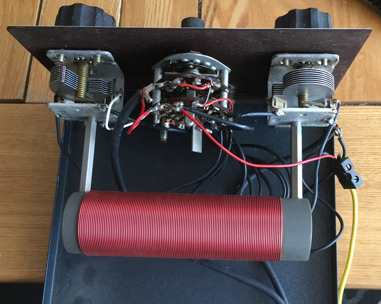
The coil tap switch and steel cabinet are shown below. I’ve rubbed down and primed the rusty cabinet ready to take the black gloss topcoat. It’s taken a considerable amount of work but I think it will be worth it in the end as it’s a nicely built unit. Does anyone recognise it? Make, model?
-
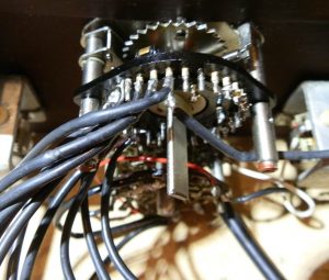
- ATU Coil Switch
-
- Steel cabinet primed
Reassembling the ATU, below. The unit is now mounted on its base. The steel cover has been sprayed and will be bolted in place very soon. I need to label the configuration switch, top centre, to show Pi – L – Series tuned circuit. Parallel tuned circuit and Off. I’ll probably rewire the off position to short the aerial to earth rather than leave it floating.
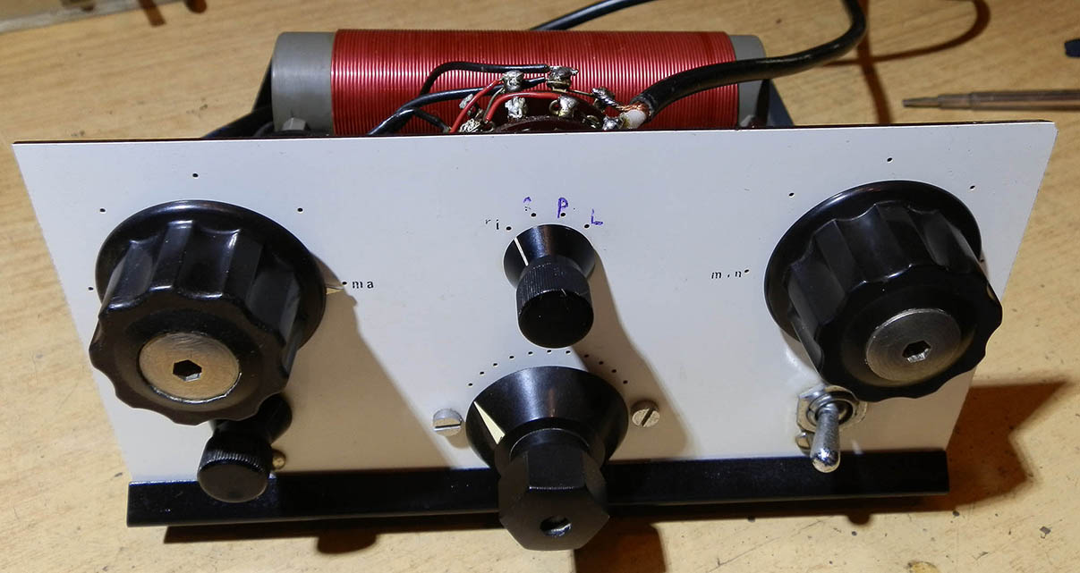
The ATU ready for service. I have to say I’m rather pleased with the result. Once the Letraset arrives, I’ll label the configuration switch positions.
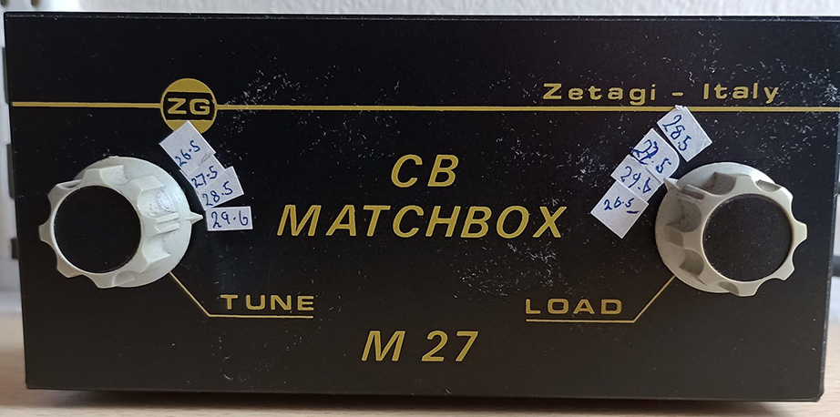
Zetagi CB Matchbox ATU:
This is a simple Pi network ATU for CB radios to be used in conjunction with an SWR meter. It covers 27 to 28MHz and will keep the rig happy if the SWR is too high. The coil could be adjusted, the windings stretched out or pushed closer together, to change the frequency coverage slightly. Thanks to Barry for the photos.

Home brew L Match.
Below is my home-brew L-Match ATU. I knocked this up many years ago to match an end-fed wire on top band, and it was perfect. I still have it, collecting dust on a shelf.
Here’s another one I made, this time with a small rollercoaster. I used this to match a 40 foot vertical aerial. The base of the vertical is on a wooden block which is on a brick. All rather temporary!
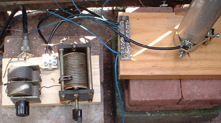
This is how the base of the aerial ended up… on a railway conductor rail insulator!
The L Match ATU:
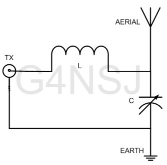
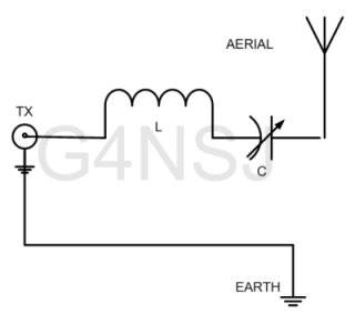
A simple L-match is shown in the circuit above, left. This is the arrangement I use to match my 150 feet of end-fed wire. L is a roller coaster and C a wide-spaced variable capacitor, about 500pF. From 80 metres to 10 metres, I get a perfect match.
For 160 metres, I have to switch the capacitor in series with the aerial and short out the coil, as in the diagram above, right. This is because my wire is too long for top band, resonating somewhere near to 1.6mHz. Effectively, a coil in series with a wire aerial electrically lengthens the aerial, and a capacitor is series electrically shortens it.
The aerial socket on the back of your transmitter wants to ‘see’ fifty ohms. And this is exactly what it does ‘see’ when it ‘looks’ into the AMU circuit. Before you grab some bits out of the junk box and build this matching unit, there are a couple of things to bear in mind.
Depending on the frequency you are using and the length of your end-fed aerial, the feed impedance of your aerial may be very high or very low. If your aerial happens to be one half-wavelength at your operating frequency, the feed impedance could be in the region of 5000 ohms. Does this matter? If the aerial matching unit is good enough to match this impedance then, no, it doesn’t matter. What does matter are the high voltages present at the feed point. The variable capacitor will flash over unless there is a sufficient gap between the vanes or plates of the capacitor.
Unfortunately, decent variable capacitors are hugely expensive and there are virtually none around on the secondhand market. However, you’re going to have to get your hands on one somehow. High voltages will also be present in the coil. A flimsy thing would with very thin wire on a cardboard toilet roll tube will probably catch fire. Imagine, when you are constructing your aerial matching unit, that it will be dealing with 1000 Volts or more and you shouldn’t go far wrong.
Just out of interest, the variable capacitors used in the final stages of high power transmitters are placed in a vacuum. This way, the capacitors may be relatively small. By small, I mean taking up several feet rather than an entire room. An electric arc needs oxygen to survive. Take the air away, and you will drastically reduce the possibility of arcing. A vacuum is also used for high voltage switching on the national grid. On lower voltage circuits of around 33kv, the switch contacts are immersed in oil.
What does make me laugh, and annoy me, is the way manufacturers rate their tuning units at 1kw or more when they’re using what amounts to broadcast receiver variable capacitors in their so-called ATUs. These capacitors were great in the old mains radios. But they have very little spacing between the vanes and are liable to flash over when loading an end-fed wire which is voltage-fed. The capacitors may be fine when using a current-fed aerial, but they are no good for voltage fed aerials.
THE BALANCED MATCH:
This is the ultimate aerial matching unit.
Now we come to a real aerial matching unit, the mother of matching units. This will match balanced line or single wire end fed aerials. The components used are few and simple. However, trying to get hold of them is a different matter. A split stator capacitor will cost you in the region of £80 or more, and as for the coils… Let’s not get despondent before we even consider constructing this AMU.
 Split-stator capacitors are used to preserve balance across the circuit. The split stator capacitor problem can be overcome by using two separate capacitors ganged together.
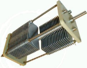
One form of split stator capacitor is shown here. Basically, this type is two variable capacitors on one shaft. The rotors or moving vanes are electrically connected whereas the stators are isolated from each other. For some reason, probably due to lack of demand, these capacitors are costly.
I was lucky enough to purchase a KW107 Supermatch ATU. This fine piece of kit is British made but, sadly, they’re no longer manufactured. If you can get your hands on one, then grab it.
The KW Supermatch has two coax outputs and two balanced outputs. It also has a built-in SWR meter and a 300 watt dummy load. With no lossy baluns in sight, this really is an amazing machine.
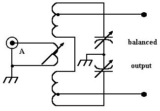
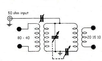 The diagram shown on the right is the basic circuit of the KW E-ZEE match and the KW107 SuperMatch ATUs. Unfortunately, I don’t have the full circuit showing switching etc. However, this gives a pretty good idea of how the thing works.
CONSTRUCTING YOUR OWN ATU:
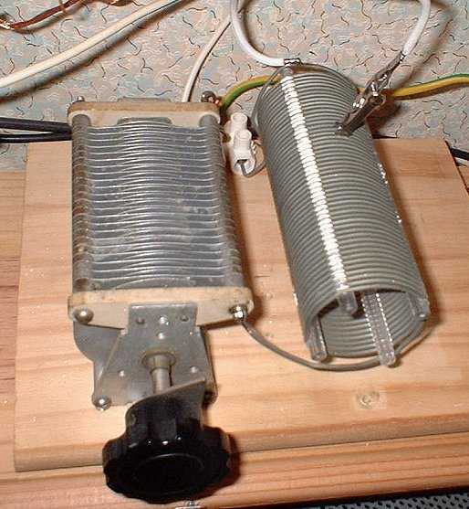
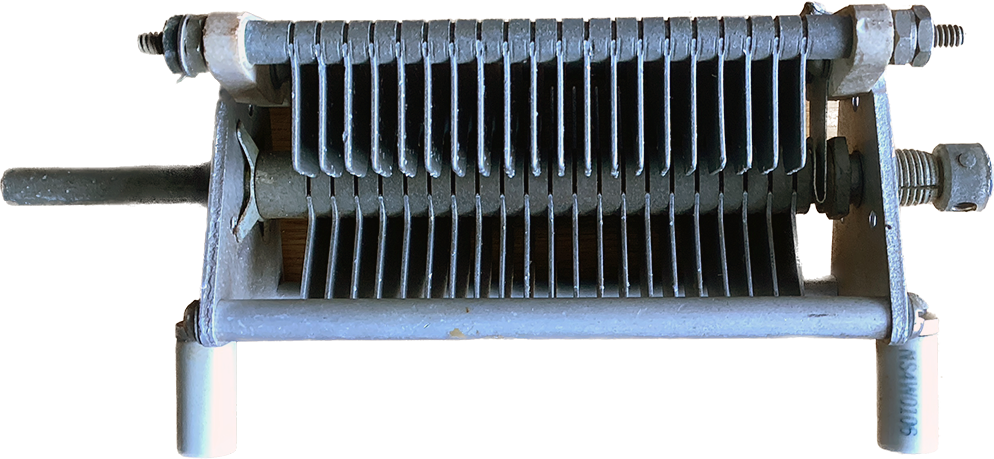
You will need decent components such as these if you are building an ATU for transmitting. The capacitor vanes need to be spaced wide apart to prevent flash over.
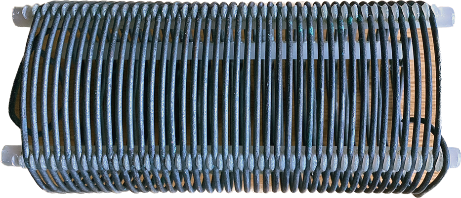
This is a beautiful tank coil. The coil wire needs to be low resistance to minimise loss and handle the current. I believe the one shown here was manufactured by Codar Radio of Southwick, West Sussex. I forget where I got it from.
Video – Setting up an ATU: