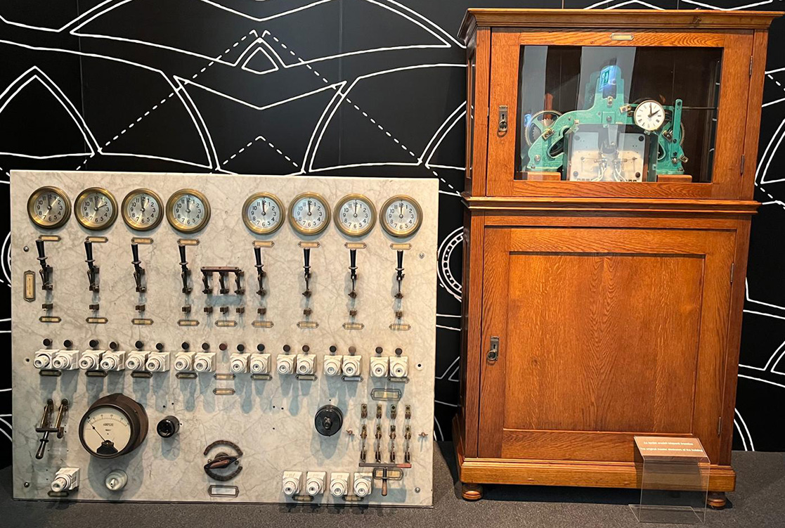
A new addition to my museum. 21/1/26:
I’ve been lucky enough to acquire a GPO Gents Master Clock No. 36 MK6. It’s an electrically controlled clock fitted with a one second beating pendulum. It supplies one second and half minute electrical pulses for the operation of slave pulse clocks and telephone equipment. It also incorporates an additional count wheel and contact springs to provide six second impulse outputs for driving Veeder clocks and telephone equipment. Clock No. 36 was introduced in 1925 to meet the requirements of new automatic telephone exchanges, which required a six-second pulse for timing and metering purposes.
Vintage master and slave clock systems were designed to provide synchronised timekeeping across multiple locations from a single, accurate source. It was used in schools, factories, railway stations, and offices from the late 19th century through the mid-20th century. These systems ensured uniform time display throughout large facilities.
The Master Clock:
The master clock serves as the primary and most accurate timekeeping device in the system. It maintains precise time and distributes synchronisation signals to the connected slave clocks. Many vintage master clocks relied on high quality pendulum mechanisms or regulated movements to achieve exceptional accuracy.
Signal Transmission:
The master clock generates electrical timing pulses at fixed intervals, commonly once per half minute. These pulses are transmitted via wired connections to all slave clocks in the system. The impulse operated a solenoid which mechanically moved the minute hand forward by half a minute, ensuring consistent synchronisation.
The Slave Clock:
Slave clocks rely on the master clock for time accuracy. Depending on their design, slave clocks may contain a basic movement that is periodically corrected or may depend entirely on the master clock’s signals to advance their hands.
Synchronisation Process:
Slave clocks receive electrical impulses from the master clock that advance or correct their time. Some models move their hands forward incrementally with each pulse, while others receive periodic correction signals to maintain alignment with the master clock.
Wired Systems:
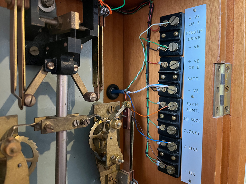
The vintage master slave clock systems typically used dedicated electrical wiring. This wiring allowed reliable signal transmission over long distances within large buildings or campuses. I’ve wired up the connections, shown below, ready for the slave clock etc. The Drive Magnet requires 4 Volts to operate correctly. This may seem odd but it’s because two glass-type 2 Volt accumulators were used in series.
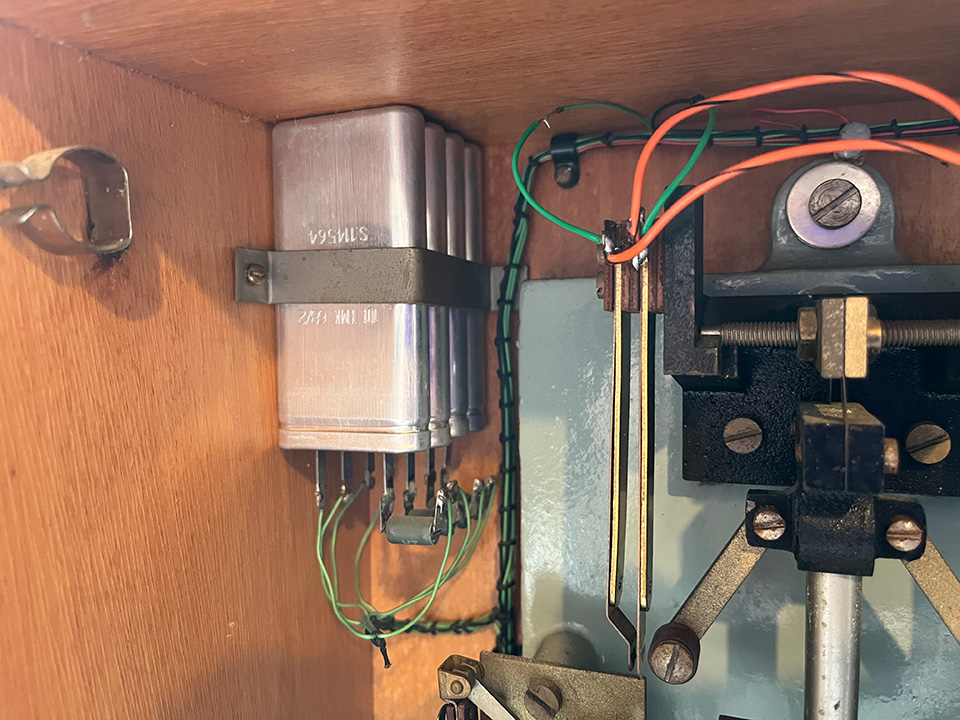
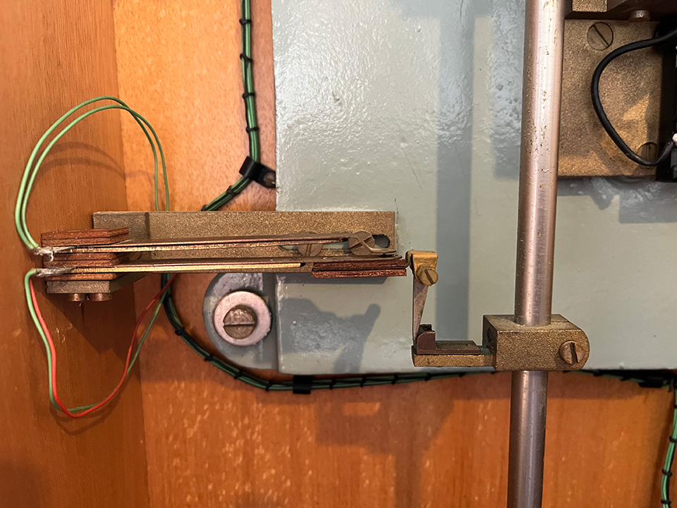
A few photos:
Left photo, spark quench capacitors and resistors connected across contacts. Centre, pendulum drive magnet. Right, Hipp Toggle. Click photos for larger image.
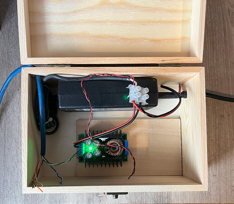
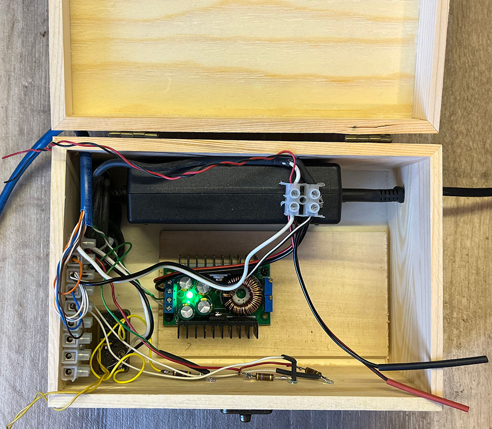
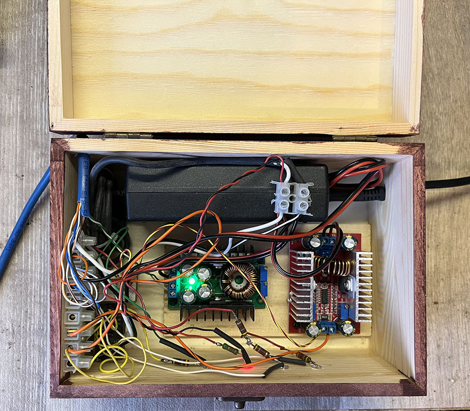
The Power Supply:
I’ve built the power supply into a wooden box as it will sit on top of the clock case and be on display. Once stained and polished, it shouldn’t look out of place. The main power supply provides a 12 volt output. The buck converter on the left supplies 4 volts for the drive magnet, while the one on the right supplies 24 volts for the slave clock. The master clock’s 30 second contacts energise a relay, whose contacts then deliver the half-minute pulses to the slave clock. An 8-core Cat6 computer cable is used to connect the clock to the PSU. Although the conductors are thin, the current involved is minimal. It looks rather messy at the moment, but it will be all right on the night! Click the photos for a larger image.
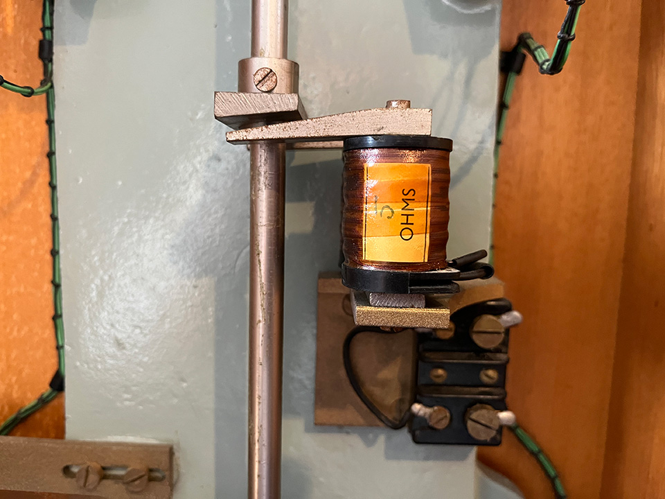
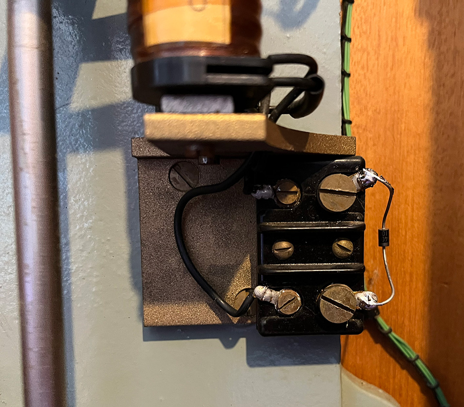
Pendulum drive magnet:
Back EMF (Electromotive Force) occurs when the current flowing through a solenoid coil is interrupted. This sudden change generates a high voltage spike due to the collapsing magnetic field around the coil. The voltage can be significantly higher than the supply voltage. To protect against back EMF, I’ve fitted a diode across the coil. The diode, known as a flyback diode, allows the current generated by the back EMF to circulate through the coil and the diode, preventing a voltage spike. This has also stopped the coil making a loud clunking sound when the contacts open.
Important:
The pendulum must be perfectly vertical. I found that the clock was losing time because the pendulum was way out. The clock should be mounted on the wall, but I’d rather not do that as I’m not sure if it’s final resting place. I might make a wooden base with four adjustable feet to stand the clock on.
Interesting information:
Thanks to Vic for the GPO Clock information here.
The circuit diagram:
As you can see, the circuit is not complicated. The resistors and capacitors are for spark quenching across the various contacts.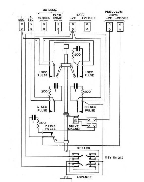
Update 9/2/26:
I now have a slave clock 70A and a BT slave clock 96A. The 70A comes in a beautiful wooden box which I will clean up and mount on the dining room wall. The 96A will go on the wall above the mantelpiece. See here for details.
The Master Clock Video – Part One:
The Master Clock Video – Part Two
The Hungarian Parliament Building Master Clock:
The master clock of the Hungarian Parliament Building in Budapest is an example of 19thcentury electrical timekeeping. The clock mechanism controlled a network of clocks throughout the building. Instead of winding and setting each clock manually, all the clocks were synchronized by this one master device. The system controlled over 100 slave clocks located in halls and offices. The master clock was originally placed in the library.