This is one of the simplest, ancient, and effective aerials around. When cut for a single band, it can be fed with 50 ohm coax without the need for an aerial matching unit. I use a half-wave dipole on the five meg frequencies. It’s only 16 feet high and about 88 feet long, and works extremely well.
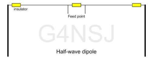
A dipole can be fed at any point but the centre, being around 72 ohms impedance, is the usual feed point. The dipole can be fed with coax, which is useful, and low impedances are easier to match than a few thousand ohms.
As I said, for single band use, this is one of the simplest aerials around. We’ll fire up on 20 metres and work some DX but, first, we have to work out the length of the two elements. You’ve probably heard of the velocity factor and free space and all that. Don’t worry about it.
There’s a simple formula for working out the length of a half wave dipole. The centre of the 20 metre band is around 14.175 mHz. So, we divide 468 by 14.175. That gives us 33. The beauty of the formula is that the answer is in feet – 33 feet. This is the overall length of the dipole, from end to end. So, each element is 16.5 feet long.
Don’t worry too much about cutting the wires to the exact length. In fact, make them a foot or so longer. Once the dipole is up in the air, you can trim the wires by an inch or so at a time to bring the SWR down to one to one. Before checking the SWR and cutting the wires, remember that the aerial must be in its final position. Hauling the aerial up and down several times can be awkward, but it has to be done.
The centre insulator can be made out of any suitable material but try to keep it lightweight. Before soldering the connections, coil up about 6 feet of the coax and tape it up to form a choke. This coil should be about six inches diameter and as close to the feed point as possible. This will prevent the outer of the coax radiating.
Now you can haul the aerial up and do your SWR trimming. Remember to keep both the elements exactly the same length. If you snip two inches off one end, then you must do exactly the same to the other element. If you don’t, then the thing will lose its balance and you’ll never get the SWR right. By the way, do your SWR tests on low power so as not to blow up your transmitter.
That’s about it. There’s no need for a matching until and the SWR will be good over the entire band. One more thing. If you don’t have a large enough garden, you can allow the ends of the wires to hang down. Remember that it’s the centre of the aerial that radiates most of the signal, due to the high current there. Keep the centre as high as possible and, if the thing ends up in an inverted V shape, this may be a good thing. More on the inverted V dipole later.
FEEDING A HALF-WAVE DIPOLE WITH BELL WIRE
You might laugh but bell wire or flat twin mains lead has an impedance of around 72 ohms. The feed impedance of a half wave dipole is 72 ohms. If you have a properly balanced ATU, then you’re in business. Coax is lossy and the shield is liable to radiate but, feeding a dipole with twin feeder keeps the whole system balanced. Think about it… 300 ohm ribbon is only widely spaced twin lead.
Some technical info:
The length of a half wave dipole is determined by the frequency the aerial is going to be used on. The formula for calculating the length of a half-wave dipole in feet is:
Length (ft) = 468 / Frequency (MHz)
For example, a half-wave dipole for use on the 20 metre amateur radio band, 14 MHz, would have a length of 33 feet.
When an RF signal is applied to a half wave dipole, a standing wave is set up along the length of the antenna. The maximum RF current occurs at the center of the dipole, while the maximum RF voltage occurs at the ends. The dipole radiates energy in a directional pattern perpendicular to the length of the antenna, with the strongest radiation occurring broadside to the antenna.
Half-wave dipoles are popular antennas for HF communications due to their simplicity and efficiency. They are easy to construct and don’t need a matching network when fed with 50 ohm coax.
Out of interest. In a dipole antenna, the RF current lags behind the RF voltage by 90 degrees. This is because the current in a dipole is at its maximum when the voltage is at its zero crossing, and vice versa.