5/11/25:
I’ve just taken delivery of a Racal RA-1772 communications receiver, thanks Evan. It needs a good clean and it has a few problems. However, I’ve managed to get it working. I can honestly say that this is the best receiver I’ve ever owned. The tuning control is beautiful. Resolving SSB is amazing. Once I’ve finished cleaning and restoring the receiver, it will take pride of place in my radio room.
The receiver covers 15kHz to 30MHz. It actually tunes down to about 12kHz, which is great for VLF listening. Antenna input via BNC socket, 50 to 75 ohms. Unfortunately, I had to replace the BNC socket as the inner connection broke up. All is well now. I’m using a Miniwhip active antenna with the receiver.
The Racal RA-1772:
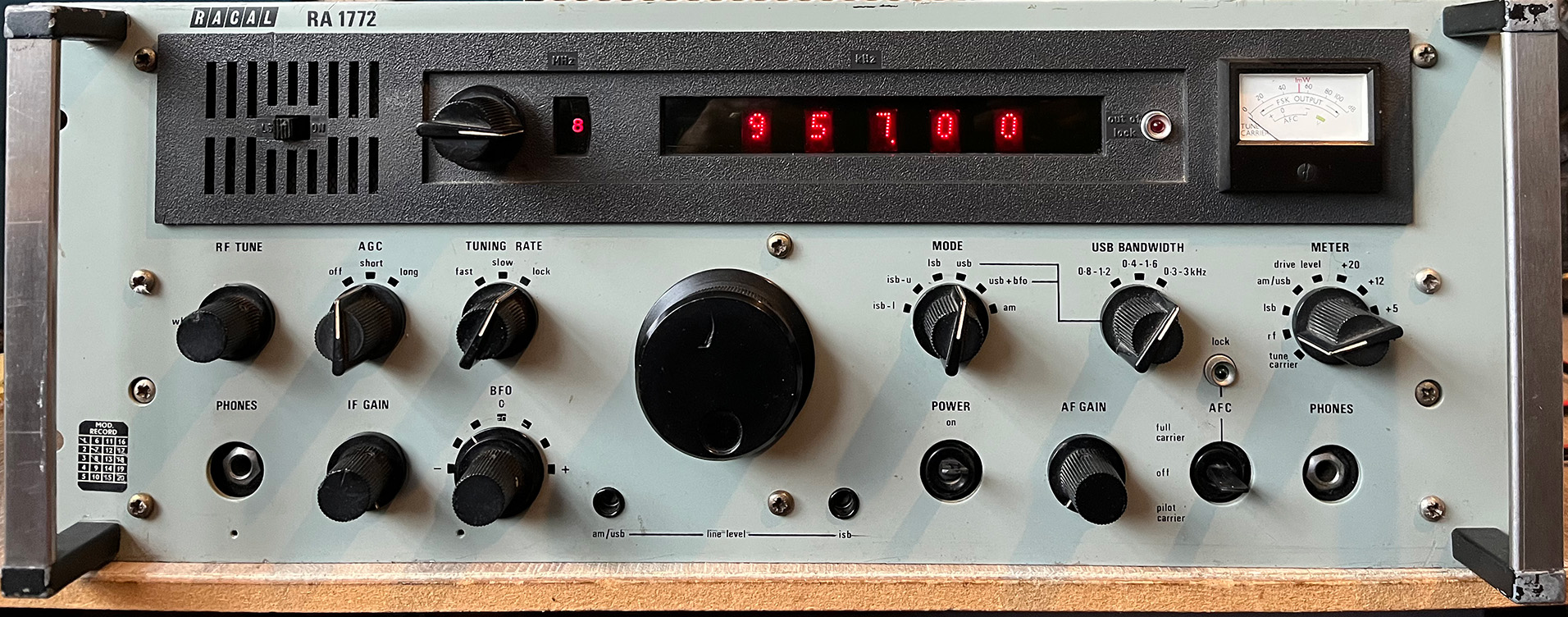
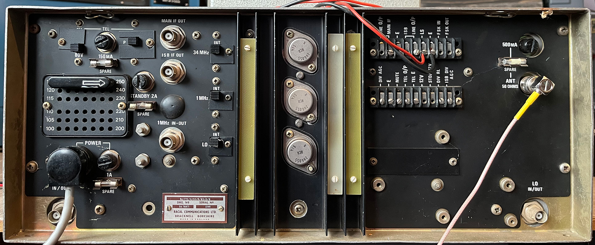
Below. Back panel:
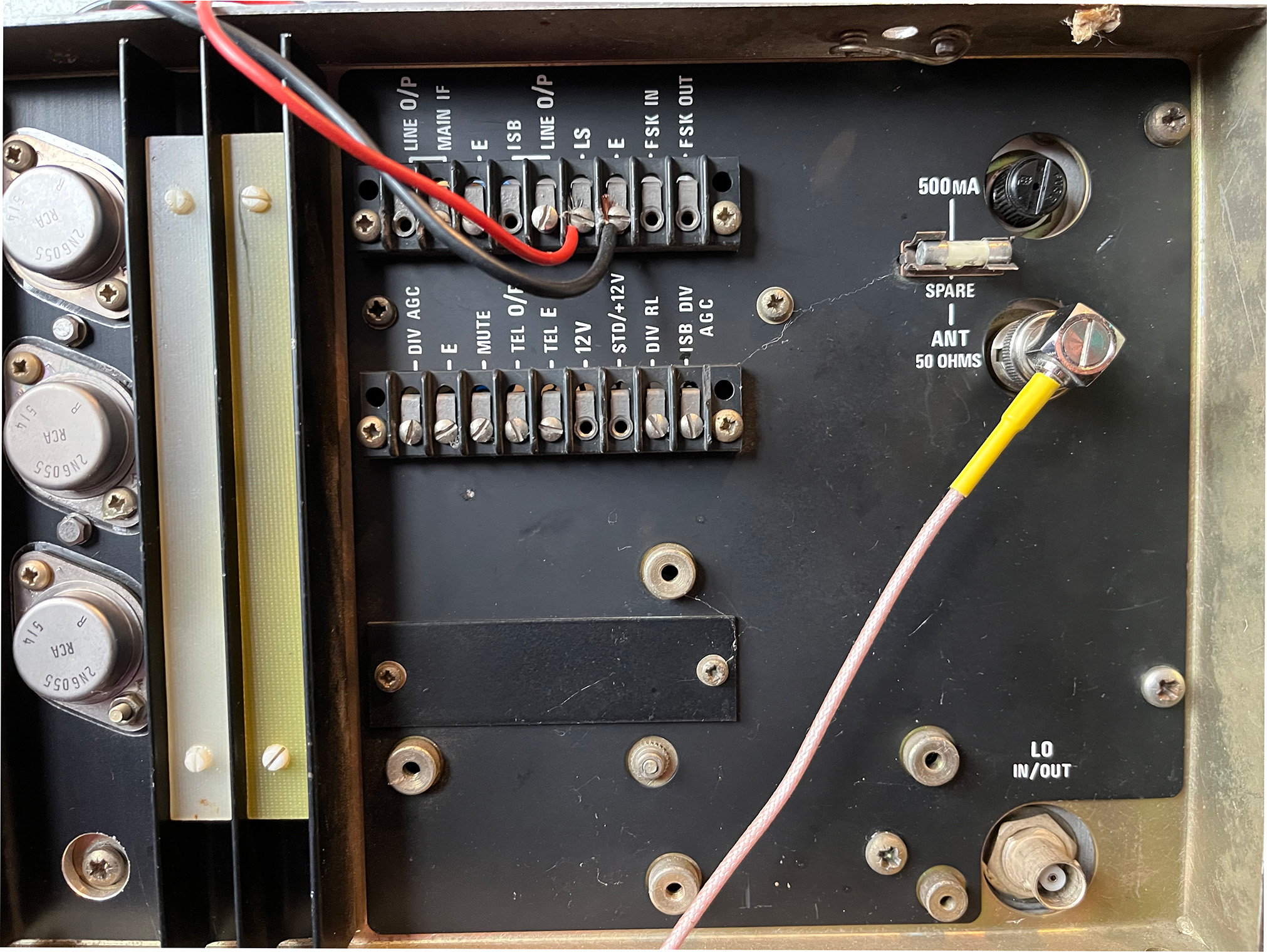
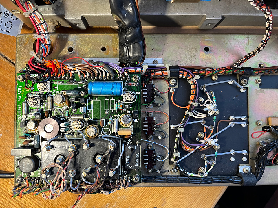
The back of the radio is packed with goodies.

Power supply problems:
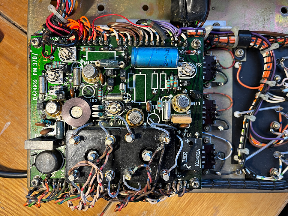
There were several power supply problems. The 20 volt rail dropped to about half voltage at times. I discovered that there were several intermittent connections on the power supply board. They were mainly caused by heat from one of the bridge rectifiers. There was also an intermittent hum or, what’s better described as, a gurgling sound on SSB signals. I cleaned the pre-set pots on the main PSU board, left-hand photo, and the three slide switches just to the right of the board. Also shown at the bottom of the main board are the two bridge rectifiers. One was running very hot, so I bolted a new replacement to the chassis. The work completed, all traces of hum and gurgling disappeared and the 20 volt rail was stable.
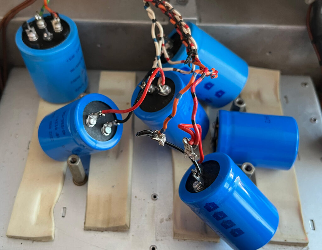
I replaced all six smoothing capacitors. They were 50 years old so they’d done well. According to various forums I’ve read, power supply problems are common on the RA-1772. However, the receiver is now working well with none of the original problems showing up. The mains transformer hum became increasingly louder over the weeks. This suggested excessive current drawn from the transformer. Once the bridge rectifier had been replaced, the hum disappeared. I reckon that one of the diodes in the bridge was failing.
Independent Sideband (ISB):
This refers to a mode of operation in which each sideband of a double sideband (DSB) signal carries separate information, and the receiver is designed to demodulate them independently. Normally, in amplitude modulation (AM), both the upper sideband (USB) and lower sideband (LSB) contain identical information — so one is redundant. But in ISB, each sideband carries a different program or data stream on the same carrier frequency.
How an ISB Receiver Works:
An ISB receiver is essentially a dual-channel single sideband (SSB) receiver. It performs these steps:
1. RF Amplification & Mixing:
The incoming RF signal (with both sidebands) is amplified and mixed down to an intermediate frequency (IF).
2. Sideband Separation:
The IF signal passes through two filters — one for the upper sideband and one for the lower sideband.
Each filter isolates its respective sideband and rejects the other.
3. Independent Detection:
Each sideband is then demodulated separately, usually using product detectors or synchronous detectors.
4. Separate Audio Outputs:
The receiver provides two independent audio outputs, one for each sideband.
These can be sent to two speakers, two recording channels, or two different circuits.
Independent Side Band was used by broadcasters, such as the BBC and the Voice of America, for feeding programmes to overseas relays. It used reduced, not fully suppressed, carrier. This gives a reference point for accurate tuning and, if necessary, something for the automatic frequency control to lock onto. The upper and lower sidebands then carry two completely separate programmes.