The BALUN:
An HF balun, balanced to unbalanced, also known as a current balun or voltage balun, is used to match the impedance of an aerial to a transmission line. What’s the point of an HF balun? It’s to convert the unbalanced signal from a coaxial cable to a balanced antenna such as a dipole, or vice versa. This is achieved by using a transformer that has a different number of turns on each side, with the ratio of turns depending on the desired impedance match and balance… a balun.
There are two types of baluns: current baluns and voltage baluns. A current balun is designed to block common mode currents from flowing on the feed line, while a voltage balun is designed to balance the voltage on the feed line. Both types of baluns can be used for impedance matching and balancing, but their performance may vary depending on the specific application and operating conditions.
HF baluns can be designed and constructed in a variety of ways, including using toroidal cores, air cores, or ferrite cores. They can also be constructed using different materials, such as copper wire, coaxial cable, or other types of conductive material.
The UNUN:
An HF unun, unbalanced to unbalanced, is a type of transformer used to match the impedance of an unbalanced load, such as an end-fed wire, to an unbalanced feed line, such as a coax cable. Unlike a balun, which is used to match the impedance of a balanced load to an unbalanced feed line or vice versa, an unun is designed to match the impedance of an unbalanced load to an unbalanced feed line. See video below.
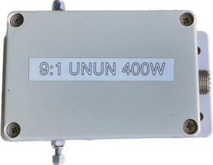 The advantage of an HF unun is that it can provide a more efficient impedance match for certain types of antennas, such as end-fed wires, than a balun. This is because the unun can provide a better transformation ratio between the high impedance of the antenna and the low impedance of the feed line, resulting in less signal loss and better antenna performance.
Like baluns, HF ununs can be constructed using different types of materials and designs, depending on the specific application and operating conditions.
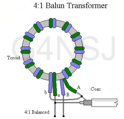
The diagram below shows the 4:1 balun. The number of turns depends on the thickness of the wire and the size of the ferrite ring. Around 18 turns is a good starting point. You can always add or remove turns if things don’t look too good.
Common Mode Chokes:
Below is a common mode choke that I wound to cover the HF spectrum. See the video below for details…
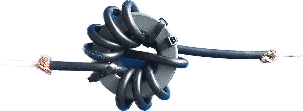
A coax common mode choke is aused to suppress common mode noise in coax cable. Common mode noise is electrical interference, which is a real pain, that travels along the outside of the coax shield. A coax common mode choke consists of a ferrite with coax cable wound round it. The ferrite core is a magnetic material that provides high permeability, which helps to reduce the amount of common mode noise that can pass through the choke. At the bottom of this page, there’s a link to a great article by Steve Hunt which explains this far better than I can.
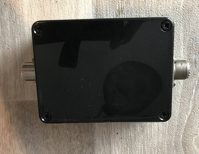
The choke finally made the journey into a box along with a couple of SO239 sockets.
Link to article by Steve Hunt here
The UNUN. A Video: