Construction of the Paraset Spy Radio begins 15/11/25:
 Thanks to my friend Roy, I’ve acquired just about everything I need to build a Paraset Spy Radio, sometimes known as the Whaddon Mark VII radio. Or, as MI6, The British Secret Intelligence Service named it, the MK7.
The Paraset is probably the most famous spy radio of World War II. It was widely used by resistance groups in occupied Europe and by British SOE (Special Operations Executive) agents dropped behind enemy lines.
The comprehensive kit of parts was put together by a friend. It even comes with enough wood to make a box for the radio. As I make progress, there will be plenty of photos and videos. It’s going to be a lengthy project but it will keep me busy during the dark winter evenings. By the way, the name Paraset is derived from Parachute Set.
The RSGB booklet, shown here, is an invaluable asset if you’re building the Paraset radio. I believe it’s available from Amazon.
The radio was the product of the Royal Signals Special Communications Unit at Little Horwood and Waddon Hall workshop in Buckinghamshire, England. The power supply was either a 6 volt battery-operated vibrator type or an AC mains unit.
This is a low power, 3 to 5 Watts, CW transceiver developed in Great Britain during the early part of World War II. It was used for clandestine communications mainly in France, Belgium and the Netherlands. It was the preferred radio used by agents in 1941-1942.
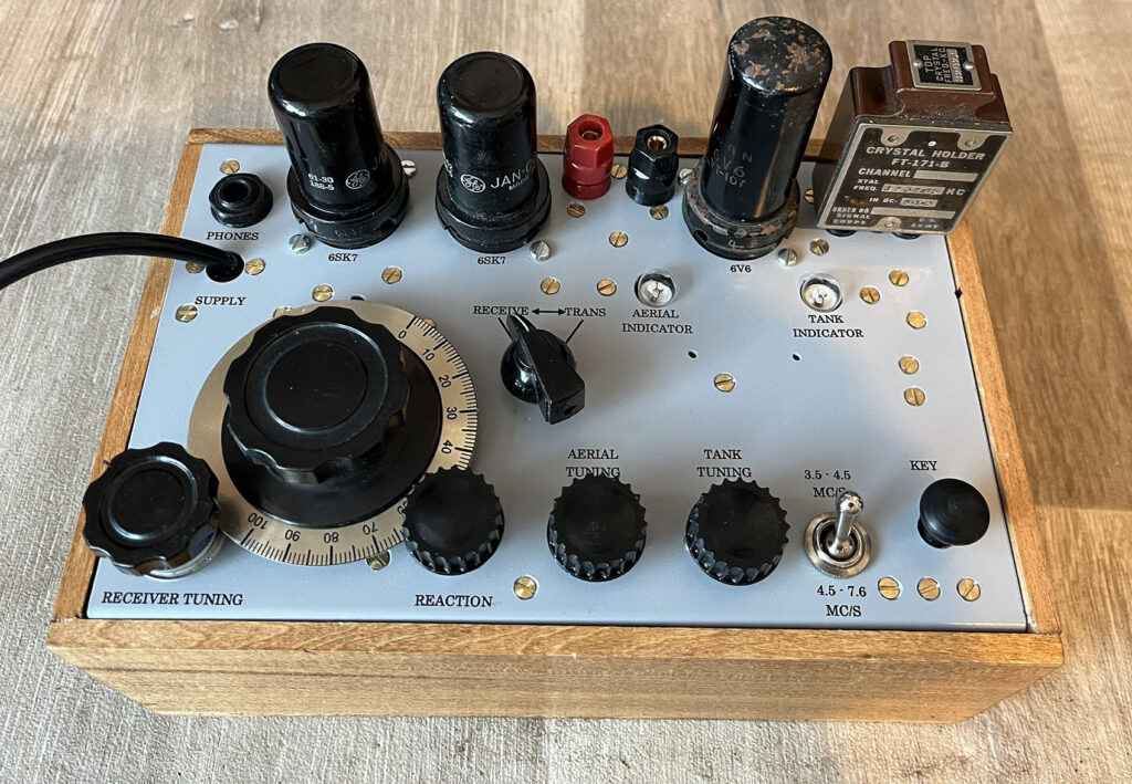
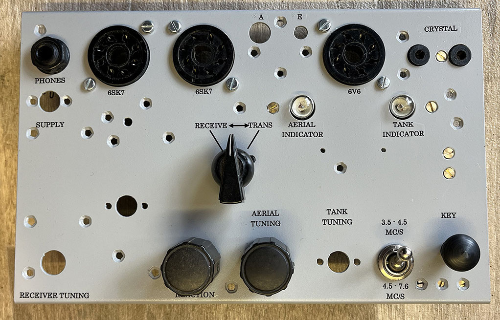
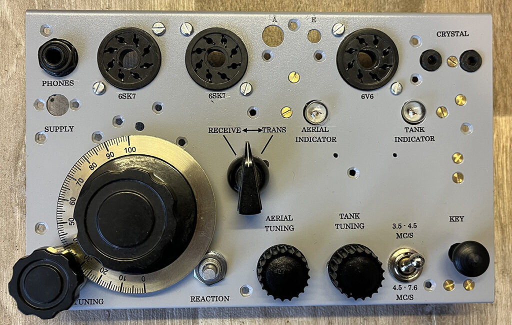
The circuit comprises a two valve regenerative receiver which covers 3 to 7.6 MHz in one band and a single valve crystal controlled transmitter covering the same in two selectable bands. Output power of the transmitter is 3 to 5 watts. Two 6SK7 valves are used in the receiver. A 6V6 operates as the crystal-controlled transmitter.
The Regenerative Receiver:
The regen receiver works by introducing positive feedback into the receiver circuit. This increases both the gain and selectivity of the receiver. The RF amplifier has a feedback loop that injects a proportion of the output back to the input. The signals in this loop are in phase with the incoming signal. A signal picked up by the antenna will be repeatedly amplified, which increases the level of gain by up to 1000 or more.
When receiving CW signals on the Paraset Receiver, the level of feedback should be adjusted so that the circuit oscillates. By tuning the receiver a few hundred Hertz away from the signal, the oscillation in the receiver mixes with the incoming signal to provide a beat note which is heard in the headphones.
Radio Direction Finding:
As the operator tuned for a signal, the circuit was adjusted just below self-oscillation, creating a to detect incoming Morse code. However, even in receive mode, this feedback caused the receiver to emit a faint RF signal, acting like a weak local oscillator. This “regen radiation” radiated from the set.
German RDF Exploitation:
The Germans deployed sophisticated mobile and fixed RDF vans with equipment tuned to SOE frequencies. They could triangulate the weak regen signal from up to several kilometers away, even if the Paraset’s transmitter wasn’t active. For this reason, the design was changed from a wooden box to a metal box which screened the circuitry.
Bletchley Park:
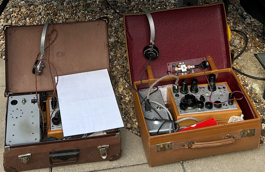
I took this photo on one of my visits to Bletchley Park. Unfortunately, the radio on the left is obscured by a sheet of paper. The right hand photo shows an external Morse key and a pair of S. G. Brown high Z headphones.
The Paraset kit:
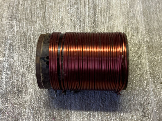
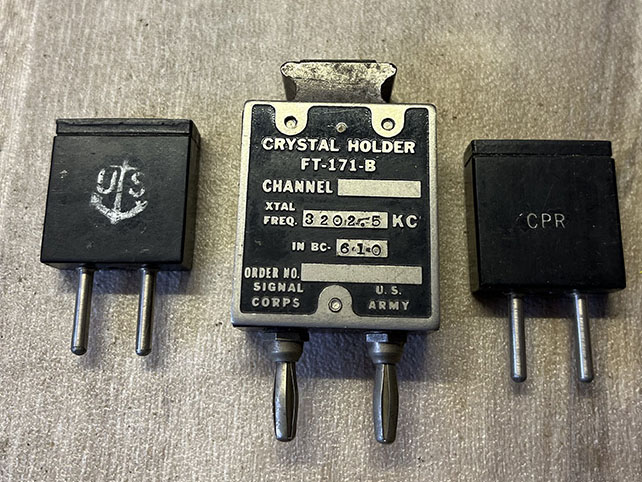
Photos of some of the parts included in the kit. Left, coil. Centre, crystals 7010kHz 3202.5kHz and another 7010kHz. Right, Morse key.
A 3759kHz Crystal donated by Keith:
Thanks Keith for sending me this crystal. It’s the wrong part of the 80m band for CW but it will be great for testing the Paraset.

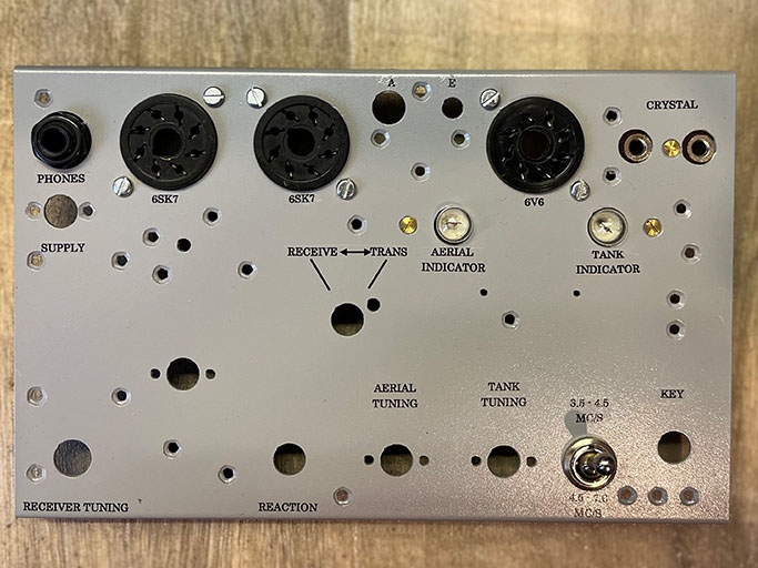
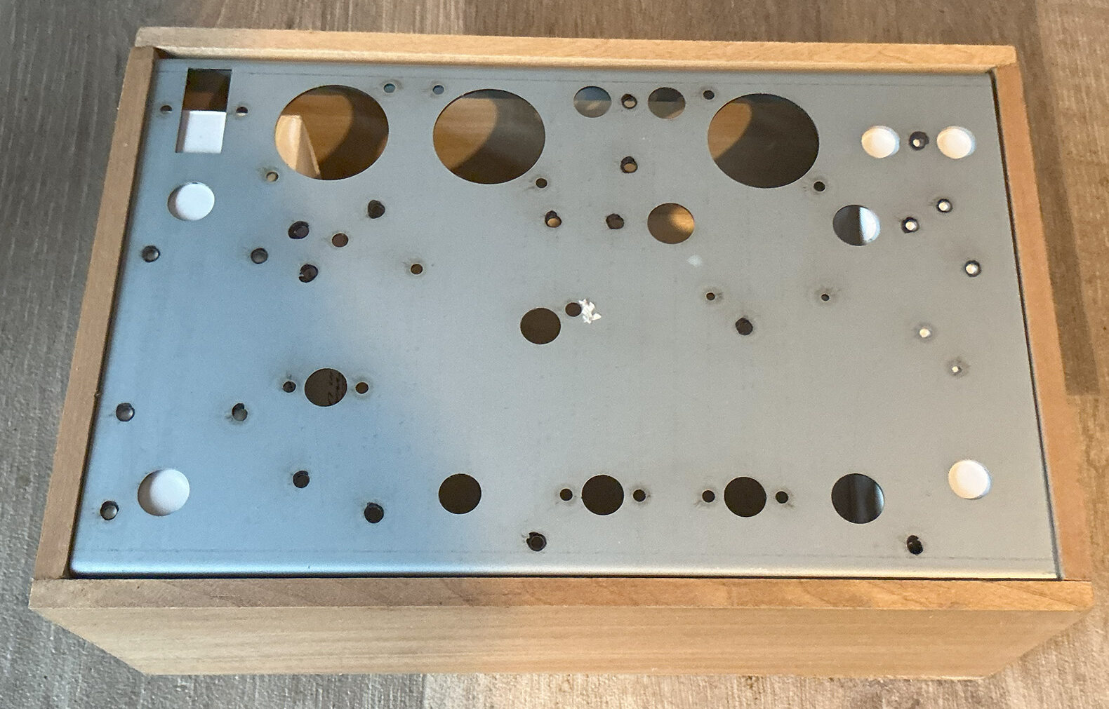
The chassis plates:
The left plate is for a wooden box type radio. The right plate is for a metal box type radio. You’ll notice that the plates are different. The left one has been drilled for a round brush socket, which I thought was for a power connector. I’ve just had a reply from the Paraset Guy. He tells me that the brush connector was not used for power but for crystal earphones. He had some of the sockets made to fill the hole and keep the unit looking original. He didn’t have plugs made because no one has the original crystal earphones. From the photos I’ve seen online, the power cable entered the wooden box on the right hand side.
The chassis on the right has a rectangular hole for a Jones-type power connector. There were two plates amongst all the bits and pieces so, at some stage, I’ll build a second Paraset radio.
Mk VII. In wooden enclosure.
Mk VII/2. In metal enclosure.
Battery Power Supply:
This is a homebrew 12 volt battery supply for use in place of the original vibrator pack. There was even a mains transformer included with the parts so I shall be building a 230v mains PSU at some stage.
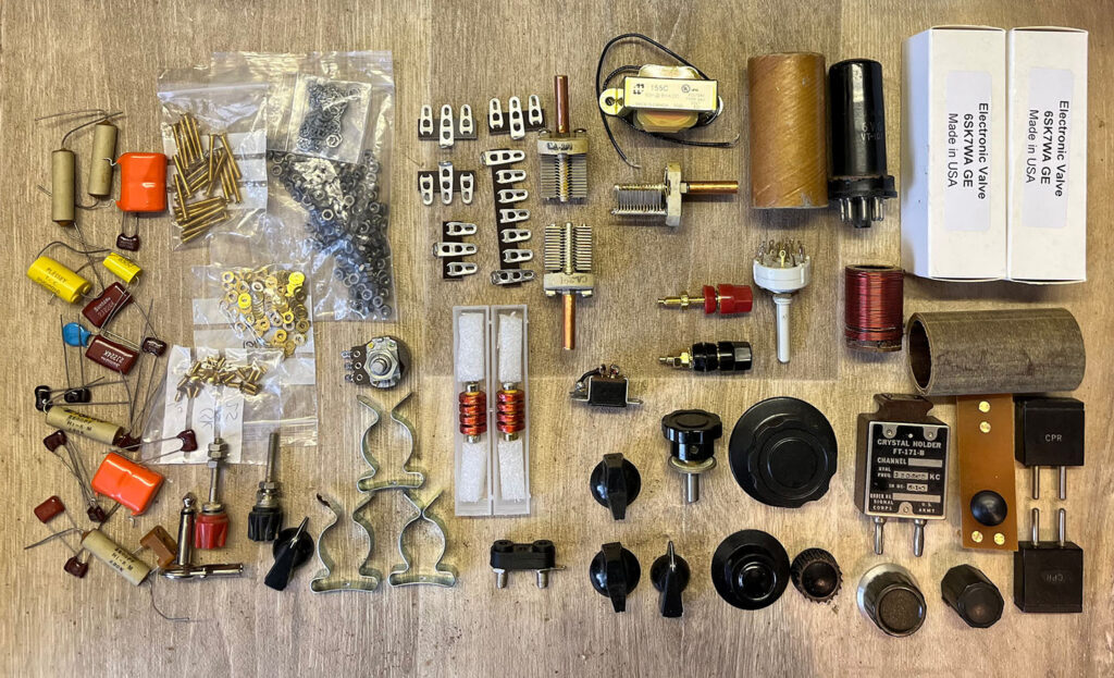
The Paraset Kit:
Here are some, not all, of the parts included in the kit. Other parts are switches, resistors, vernier dial etc.
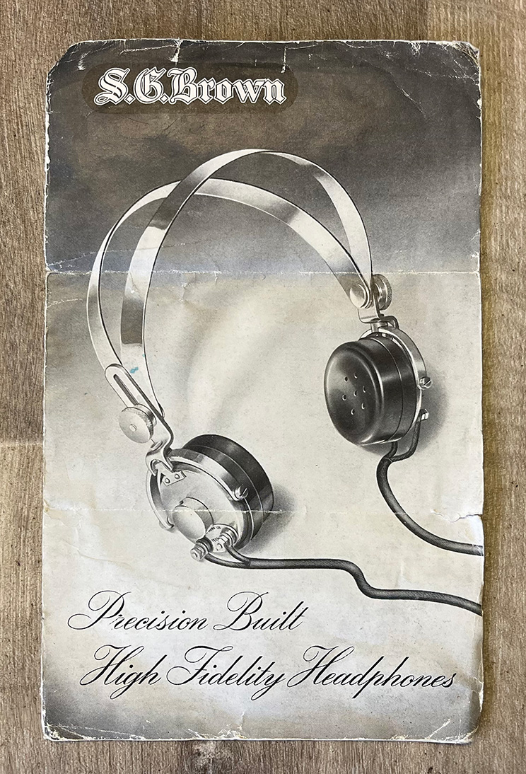
S. G. Brown Type F Headphones.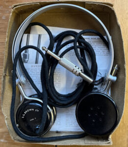
Genuine S. G. Brown high impedance headphones are becoming rare these days. However, I was lucky enough to find these included with the kit. They will accompany the Paraset perfectly. Also, now that I have decent high Z phones, I’ll look at building a crystal set. I used to make these little radio sets when I was at school but that was years ago. I think it’s time to build another one. There again, I think I have enough on my hands for now. Let’s get the spy radio up and running first.
Sidney George Brown set up a business in Watford, North of London, in 1910. In 1915 he moved to a larger factory in North Acton, London. The company continued making headphones until the 1960s. In the 1980s, it became part of the Racal organisation.
S. G. Brown catalogue, box and price list.
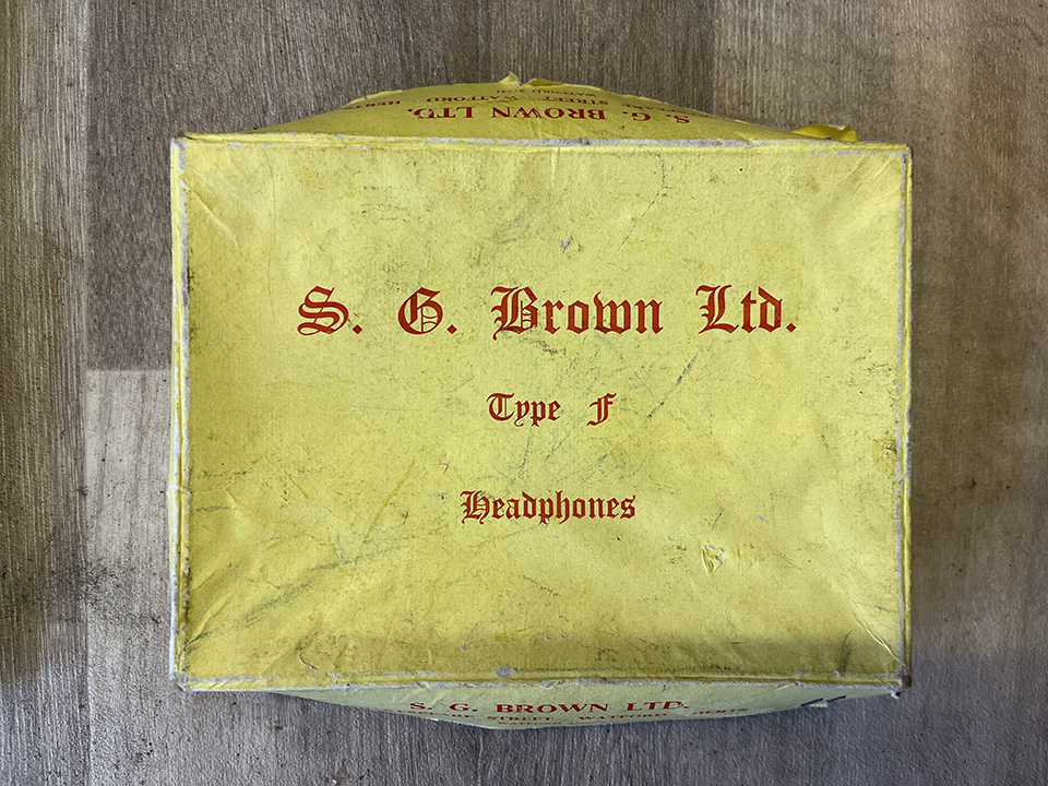
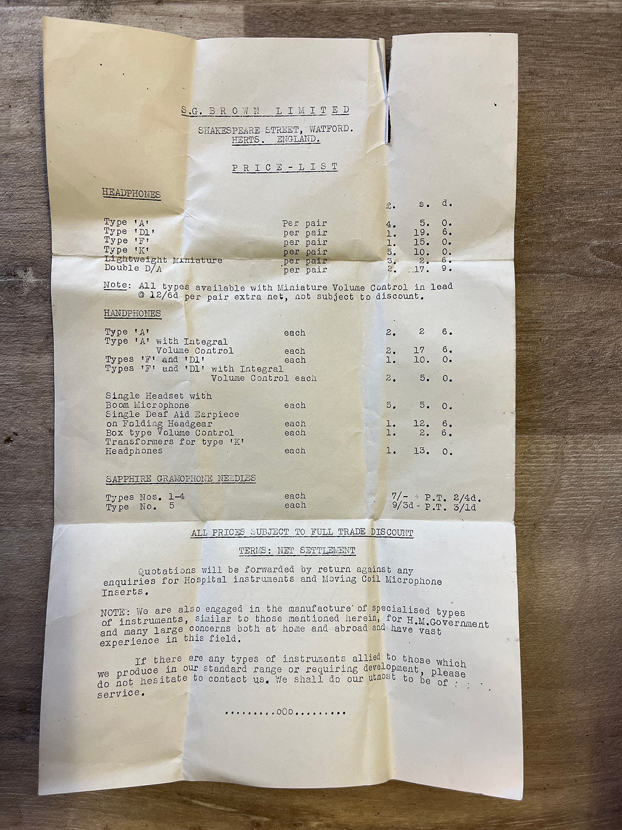
It’s a shame that there’s no date on the price list. These phones were sold at £1-15s but when was that? As we’re supposed to be talking about Paraset Radios rather than headphones, let’s move on.
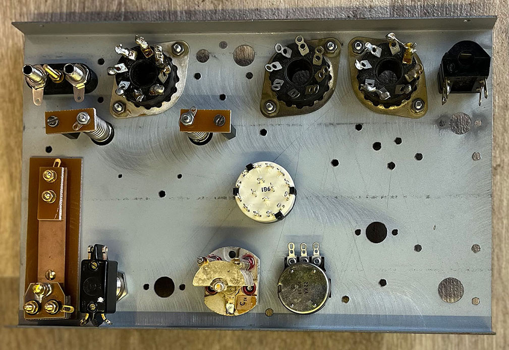
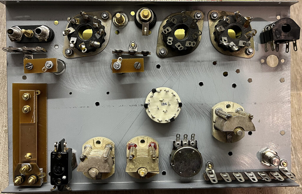
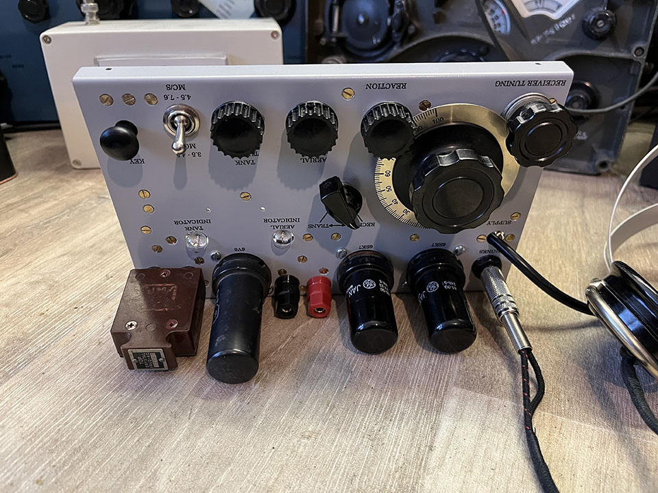
Construction begins:
I’m starting by mounting the components on the chassis. This plate was drilled for the round, brush socket, power connector, which I don’t have. For the time being, I’ll take the power cable directly through the hole which will at least get the set working until I can locate the correct connector. Unfortunately, the crystal socked securing screw hole has been drilled off centre. It’s not a problem but it doesn’t look right. Oops, I’ve fitted the wrong knobs!
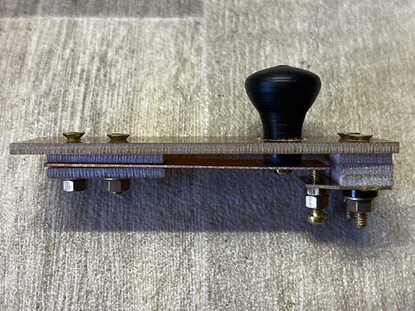
Tuning drive assembly:
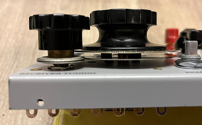 Fitting the tuning drive assembly was fun! Lining up the discs wasn’t easy but I got there in the end. I had to insert spacers between the drive disc and the dial plate and, fortunately, the whole thing fitted together nicely. And… it worked!
The reaction control pot has a very short shaft. I’ll have to find another pot with a longer shaft to take the knob. I believe it’s 25K probably linear. I’ll have a look in the junk box.
This is a very simple drive mechanism which was used on various 1940s equipment. The Wireless Set No 19 used a similar set up, as did many other war time transmitters and receivers.
The Chassis:
I have the knob for the reaction control but the grub screws are missing from all three small knobs! No problem, I’ve ordered a pack of 6BA grub screws. I’ve yet to mount the aerial and earth terminals and there are several small tag strips and solder tags to mount on the rear of the chassis. I haven’t worked out how I’m going to mount the coils but I have some stand-off insulators and other goodies among my bits and pieces.
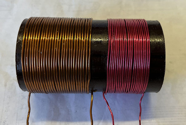
The next job is to mount the coils and the audio choke. Although the choke I have is rather large, I might just be able to fit it in.
Resistor values:
Unfortunately, the circuit doesn’t use E24 series resistors. Resistor values don’t matter too much but I want to keep the set as original as possible. Luckily, I’ve found some non-preferred value resistors on eBay. I believe the E24 series of resistors was established as part of the preferred value system defined by the International Electrotechnical Commission (IEC) in 1952. The Paraset was designed previous to this.
The Audio Choke:
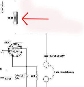 The choke that came with the kit is too large, physically. The value doesn’t matter too much but the DC resistance needs to be at least 500 ohms or more. I have noticed that some people use a conventional audio output transformer, connecting the primary from HT to the valve anode. That would enable the use of low impedance headphones from the secondary but I want to keep the radio as original as possible.
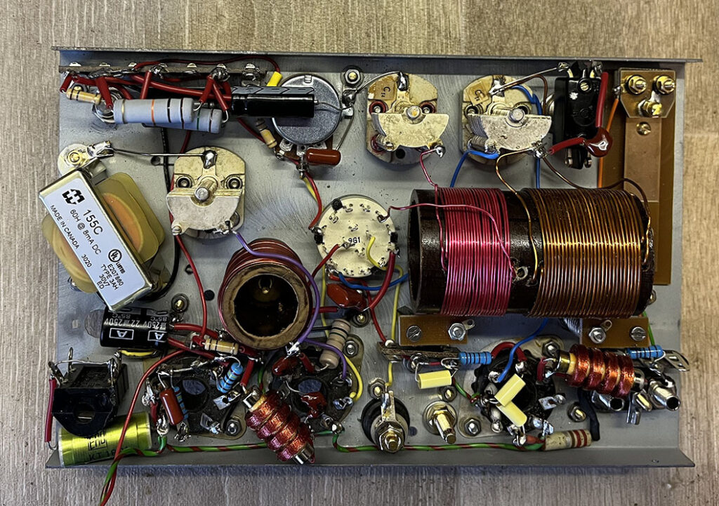
It was a tight squeeze but, I managed to fit the choke. The Paraset was designed to be compact, and its creators certainly succeeded in their quest. Compact, lightweight, easy to set up and use… hats off to the designers.
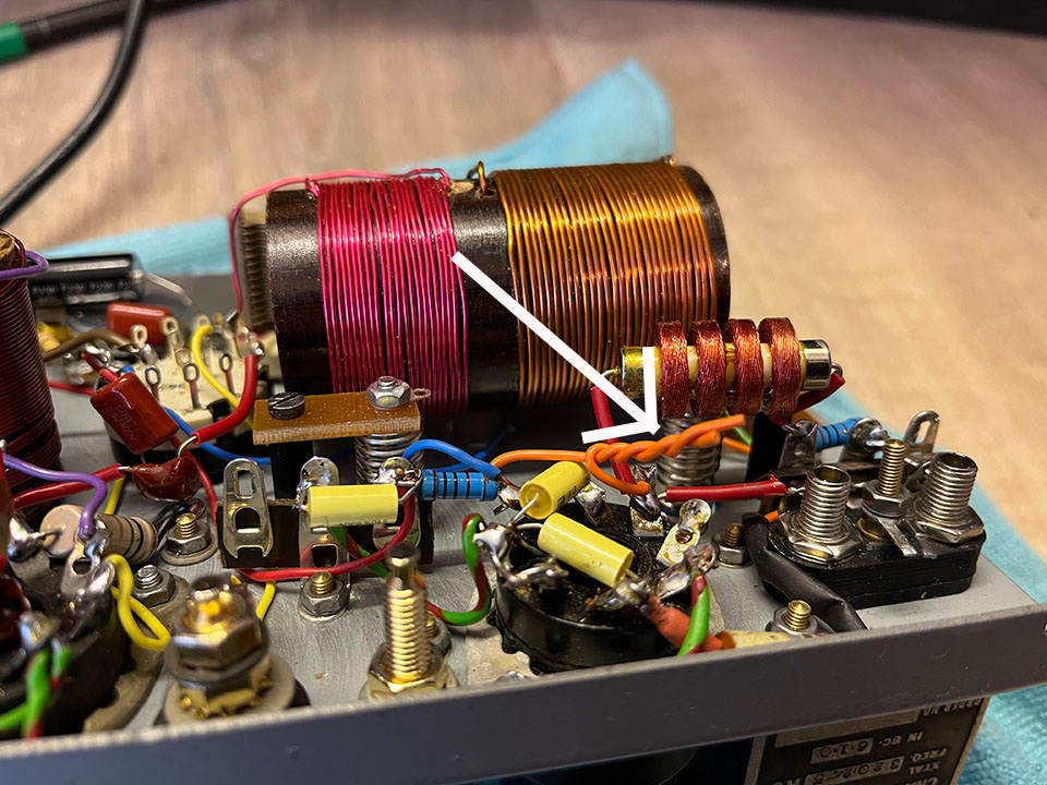
The aerial/tank coil:
I’m not very good at winding coils! It looks a bit wobbly but, it should be all right. I’ve yet to add the coupling coils for the tuning lamps. Various web sites state differing numbers of turns for the coils. I’ve wound slightly too many turns on the former to be on the safe side. It’s better to have too many rather than too few. I connected my NanoVNA to the tank tuned circuit to check the frequency coverage. It’s 3.1MHz to 8MHz so all is good.
Update 28/11/25:
Components fitted, I will now double check the wiring. Then, I will fire it up! Will it work?
Video. Building the Paraset – part one:
Update 2/12/25:
The Paraset Radio is working! Crikey, I can’t believe it! I hooked it up to a PSU and an aerial, and I was hearing things in the headphones. Switching to TX, I bashed out some Morse and the transmitter worked. I must have got a few components and some wiring in the right place.
I’ve yet to connect the tuning lamps via one turn loops to the tank and aerial coil former. Also, one of the receiver valves is microphonic and breaking down. It’s not good to hit valves, but a gentle tap is all that’s needed for the valve to take off. I’ve replaced the valve, problem solved.
The set is upside down in the photo below because it’s the only way I can prop it up. I really need to construct the wooden box because it’s very difficult to operate the set like this.
The twisted wires in the photo below introduce a small capacitance between the anode and the control grid of the transmitter valve. This anode-to-grid capacitance enhances the oscillator’s stability and frequency control, contributing to more reliable operation. For some reason, it’s known as a gimmick capacitor.
Video. Building the Paraset – part two:
Radcom circuit diagram – major mistake!
The 250k resistor from the screen grid of the audio output valve to the chassis is incorrect. As the circuit stands, there is no grid leak resistor so the control grid has no bias! The 250K should go from the control grid to chassis, effectively making the grid negative with respect to the cathode. The 75k resistor feeding the screen is correct, as is the 0.1uF capacitor decoupling the screen. I’m surprised that the people Radcom didn’t notice this.
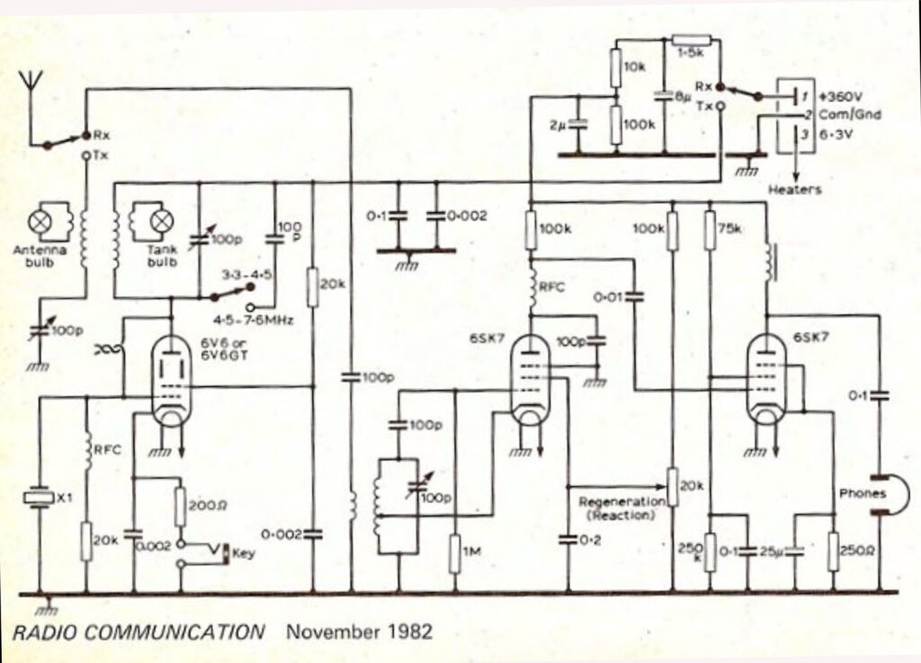
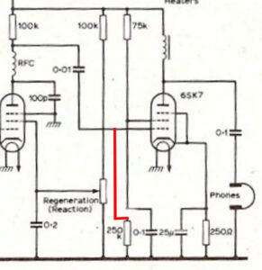
Corrected circuit below:
Remove the 250k from the screen grid and connect it to the control grid. Leave the 0.1uF decoupling capacitor from the screen grid to the chassis.
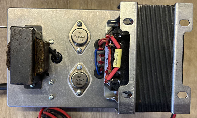
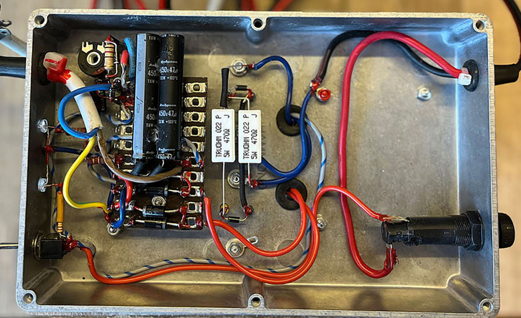
Update 3/12/25:
Now that I’ve corrected the wiring mistake and replaced the faulty valve, the receiver is working exceptionally well. When the ionosphere kicks in after dark, I’m receiving a good few broadcast stations in the 41 metre band. The problem is QRM. Christmas lights, switch mode power supplies… the noise is incredible! I’m looking forward to taking the unit away from the town into the countryside.
Update 15/12/25:
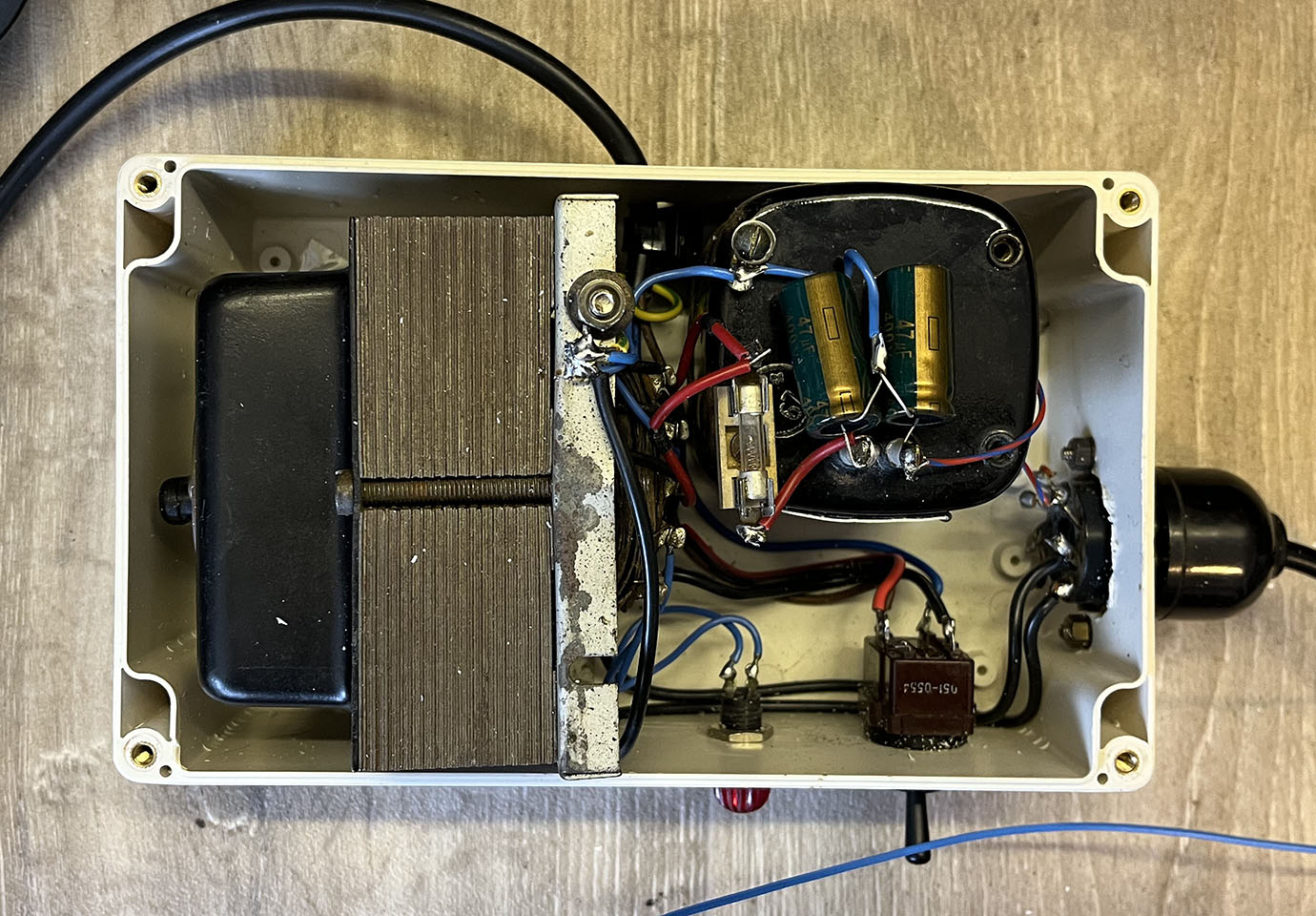
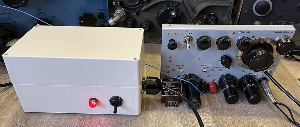
Up until now, I’ve been using the power supply I built for my HRO receiver to run the Paraset. However, I need that for the HRO receiver so I fired up the 12 volt inverter supply. Hash, oscillations, interference… I couldn’t hear a thing on the Paraset. The time had come to build a dedicated mains power supply for the Paraset. See photos below. I will have to sort out the 12 volt supply as I’ll need it for /P use.
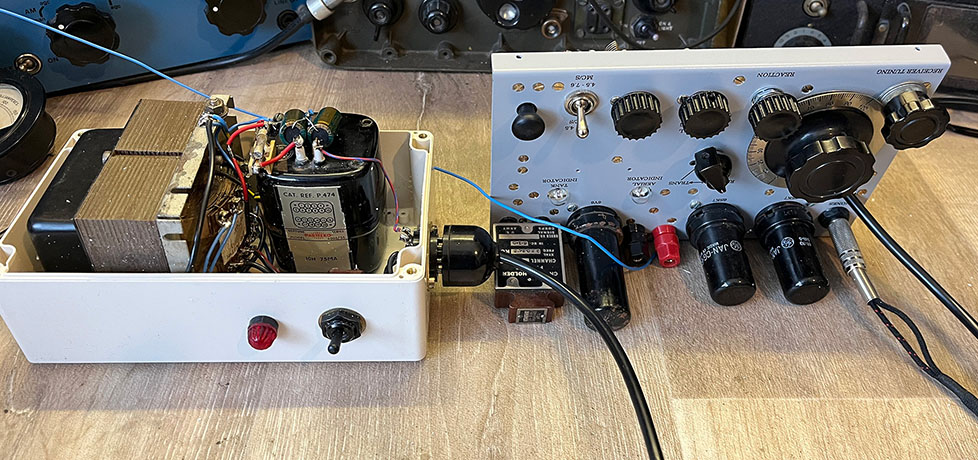
DC input power:
According to my measurements, the HT to the 6V6 on TX is 320 volts and the current is 50mA. That’s 16 Watts DC input to the stage. I haven’t yet measured the RF output power.
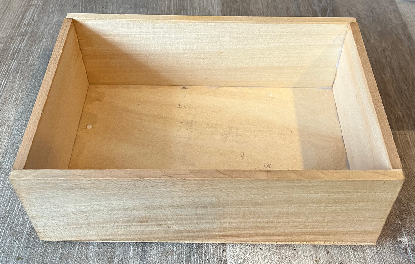
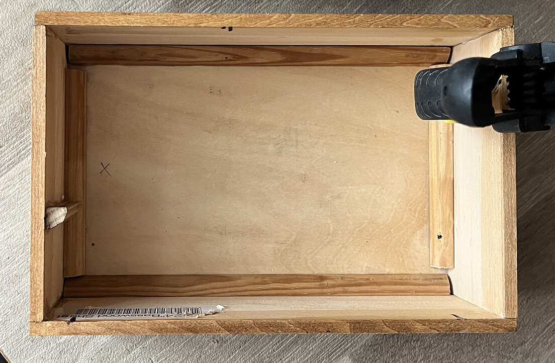
The Wooden Box:
I’ve made a start on constructing the wooden box, left-hand photo. Centre photo, I’ve dropped the blank chassis plate into the box and, miraculously, it fits quite well! What did my old woodwork teacher say? Measure once, cut three times! The right-hand photo shows quarter-round strengthening strips in the bottom of the box. Also, I’m gluing upright pillars in place for the chassis plate to sit on. I’m no carpenter, but I think it will be all right on the night.
The Wooden Box:
I’ve just about finished the project. I might fit a jack socket on the side of the box for an external Morse key. Also, I might take the power lead through a hole at the rear of the box. The 6V6 looks a little rusty. I might spray it black.