
FIRST, AN IMPORTANT WARNING!
Do not confuse an RF earth with an ELECTRICAL SAFETY EARTH. I don’t use the mains earth in my shack because all my equipment is 12 volt. However, if you have any mains driven gear, make sure that it’s properly earthed. The house wiring earth is often full of crackles and spikes and all forms of mains-born interference. While it’s best not to use this earth, you must bear in mind that all your equipment requiring a safety earth must be properly grounded. A safety earth is usually a bad RF earth. However, a good RF earth may also be a good safety earth.
MYSTERIES BENEATH THE GROUND:
I heard a chap talking on 80 metres the other evening. He was laughing about RF ground systems and asking his mate why people bother to bury miles of expensive copper wire beneath the ground simply to warm up the soil. He mentioned, all that wasted power. Earth current, he chuckled. Wasted RF current. It should be up in the air, not beneath the ground. I found it sad because he was a G3. I’m not saying that G3s should know everything. But I would have thought that their years on the air should have taught them something. How many newcomers were listening to his wholly incorrect crap? How many M3s were hanging on his every uninformed word?
Broadcast stations spend more money below the ground than they do in the air. The vertical mast with its many guy wires and huge concrete base costs a small fortune. But you can quadruple that amount when it comes to the earth mat beneath the ground. Broadcast stations are in business to make money. They do not buy miles of expensive copper wire and then bury it and pretend that they’ve scrapped it as some sort of tax loss. The Inland Revenue aren’t daft. Actually, they are. But the insanity of the Inland Revenue is outside the scope of this article.
Think of your transmitter as a voltage source. On the back of the rig there are two terminals supplying this voltage. OK, so you’ve taken a length of wire from your shack window and fixed the end to a distant tree. Great, you have an end-fed aerial. You connect the shack-end of your magnificent all-band end-fed aerial to one of the terminals on your rig. And the other terminal? What will you connect to that?
It’s the RF current flowing in an aerial that radiates the signal. Back to basics… A battery and a bulb. Wire from battery to bulb – wire from bulb back to battery. We have a circuit and, guess what? Yes, current is flowing in our circuit. So, back to your transmitter. You want current to flow in your aerial in order to radiate your signal. No circuit, no current flow. It really is as straightforward as that. How do you make current flow in the aerial? By connecting the other half of the circuit to the other terminal on your voltage source. What is the other half of the circuit? You’ve guessed it. The earth.
I was talking to a fellow amateur on top band a while ago and, like a fool, I mentioned that my homebrew RF ammeter was connected in my earth wire. You won’t get a current reading there, he laughed. There’s no RF current flowing in the earth. I tried to explain that the current flowing in the end-fed aerial should be about the same as that flowing in the earth connection. I gave up when he suggested that there was something very wrong with my ground system.
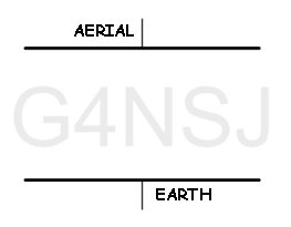 Take a look at the diagram on the left. The aerial and the earth are akin to the two plates of a capacitor. AC current flows through a capacitor, right? Our signal is AC, so it flows between the aerial and the earth, through the air. This completes the circuit. And, as we know, current will not flow in an open circuit. Without an earth connection, we have an open circuit. This also shows how and why the RF current flowing in the aerial is exactly the same as that flowing in the earth connection.
DON’T TRY THIS AT HOME!
Take a couple of wires from a light bulb and connect one wire to the live pin on a wall socket and connect the other wire to an earth rod in the garden. If your earth rod is deep enough and the soil wet enough, the bulb will light. Current is flowing through the ground, right? The more extensive your earth system, the brighter the bulb will glow. Why? Because the more rods and wires you bury in the garden, the less the ground resistance becomes. This is exactly what happens with RF. Imagine that the bulb is the aerial. The less resistance there is in the circuit, the brighter the bulb.
THE RF AMMETER
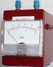 To the left is a picture of the RF ammeter. The two terminals on the top are connected together inside the box with heavy wire which runs through the centre of a toriod, forming the current transformer. The beauty of this arrangement is that you can stick the meter in the aerial wire or the earth connection. Details of the RF ammeter can be found here.
All this talk about earth currents doesn’t apply to dipoles or other balanced aerials. Why? We’ll come to that later. So, now you’re convinced that RF currents DO flow in the ground. You are convinced, aren’t you?
The earth wire running from my ground system into my shack isn’t wire at all. It’s 8mm copper pipe. The bigger the pipe, the less the resistance. The fact that the pipe is hollow doesn’t matter. Why? Because RF currents travel along the outside of a conductor. This is called the skin effect.
TO WRAP UP OR GO NAKED?
I recently conducted a survey among a group of radio amateurs in our local pub. The copper wire buried beneath the ground: does it matter whether it’s insulated or not? That was the question. The results of the survey were conclusive. There was a fifty-fifty split. Half of those taking part in the survey said it didn’t matter, the other half said bare copper wire had to be used beneath the ground, and the third half were more interested in drinking heavily and chatting up the barmaid. I found the results of the survey fascinating, even though there were only two participants.
The string of resistors in the diagram below represent your lawn. I realize that it doesn’t look much like your lawn but, to RF currents, this is how it appears. Imagine that there are hundreds of these strings of series resistors fanning out across your lawn.
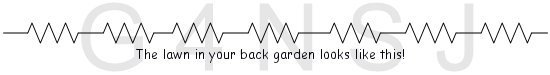
By burying copper wire beneath the ground, we are trying to decrease the earth resistance. The lower the resistance, the higher the current flow. What we are doing is shorting out the resistors in our diagram with lengths of copper wire. Now we come back to the question: insulated or bare? We’re not going to short out anything by wrapping insulated wire around it. So, that’s the answer. Go naked. The more wire in contact with the earth, the better.
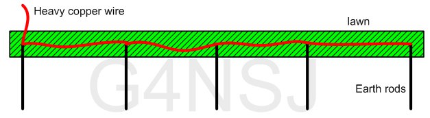
Hopefully, the above diagram looks a little more like your lawn than the string of resistors. The earth rods I used were four feet long and made of copper-coated steel. Lengths of 15mm copper pipe will do, if you can hammer them into the ground without the things bending and crumpling. The electricity companies reckon that the distance between earth rods should be equal to their length: in my case, four feet apart. The heavy copper wire should be soldered to the tops of the rods and buried just below the surface of the lawn. Cut slots in the lawn with a spade and then tread the grass back into place after burying the wire.
If possible, take several lengths of wire from your feed point rod and fan them out across the lawn, burying rods as you go. Any old pattern of wires will do, but don’t bring your copper wire back on itself connecting it to rods already used. In other words, don’t form loops between rods. The wire from your shack to the first rod must be as thick as possible. I used 8mm copper pipe.
Anorak that I am, I’ve been making a note of my earth current over the last year or so. Running ten watts on top band, I’ve taken regular RF current readings. The results? Just as I’d expected. During very dry weather, my earth current drops. When it’s been lashing with rain for a few days, the current rises. Why? Because the ground resistance decreases when the soil is wet.
COUNTERPOISE, RADIAL, EARTH WIRE… WHAT’S THE DIFFERENCE?
Again, there is mass confusion here. Let’s begin with the counterpoise. The dictionary’s definition of the word is : A counterbalancing weight. A force or influence that balances or equally counteracts another. The state of being in equilibrium. Imagine that you live on the top floor of a block of flats. Unless you run 300 feet of wire down the outside of the building to the ground, you have no earth. Despite the XYL’s moaning, you’ve slung an end-fed aerial from the curtain rail in the lounge through the hall to the shack. You will need the other half of the circuit for current to flow in your aerial. This is where a counterpoise comes in.
Sometimes called an artificial earth, a counterpoise is nothing more than a length of wire running across the floor with one end connected to the earth terminal on your aerial matching unit. This, as the dictionary states, balances your aerial system. Cut the wire to one quarter wavelength for the band is use, and you fool your matching unit into thinking that it’s seeing the other half of the aerial. As with a half-wave dipole, there isn’t an earth connection in sight.