What is RF current and does it matter?
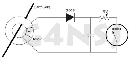
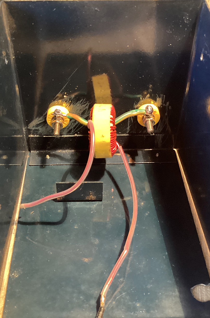
Below is the basic circuit diagram of my homebrew RF Ammeter. I would have drawn a bridge rectifier in place of the single diode but my computer circuit-drawing programme doesn’t have one. Not to worry. OK, so the heavy earth wire runs through the centre of the toroid (a ferrite ring). This doesn’t have to be your earth lead. It could be replaced by the wire from your aerial matching unit to your end-fed aerial. Contrary to popular belief, the current reading in the earth system should be the same as the aerial current. Don’t worry about that at this stage. Around the ferrite ring are several turns of thin copper wire. The more turns, the higher the meter reading. Of course, the meter reading also depends on the transmitter power and the sensitivity of the meter.
This is what happens in the circuit. RF current flows through the heavy wire running through the centre of the toroid. The toroid acts as a current transformer, the heavy wire being the primary winding and the several turns of thin wire being the secondary winding. An AC voltage is induced in the secondary. So far, so good. This secondary voltage is rectified by the Schottky diode. The meter then reads the DC voltage which you can read as RF current flowing in the heavy wire. The value of the pot depends on the meter you’re using. Start off with 100k and test the meter on very low TX power. The capacitor is 0.01uF.
-
- Homebrew RF ammeter

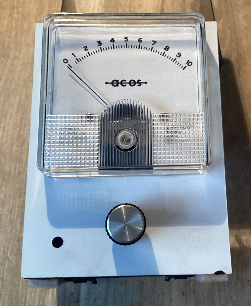
As a matter on interest, this is more or less the system used by the electricity supply companies for reading currents in cables carrying high voltages. Obviously, the meter has to be calibrated. The scale on the meter I use reads 0 to 10 milliamps. This means nothing. If I ran enough power, the full-scale reading might well equate to 10 amps. Let’s not worry about calibration at this point.
The capacitor is there simply to decouple any stray RF that may be floating around. Does this matter? Yes, because we don’t really want RF getting into the meter as it might wreck it. So, that’s basically it. The pot RV is the sensitivity control to adjust the full-scale meter reading. So, what is the point in having some indication as to the RF current flowing in your aerial or earth? And why do I have to use my RF Ammeter to adjust my aerial matching unit on 160 metres instead of the SWR meter? Why is my SWR meter bloody useless on top band? More to the point, why am I sitting here writing this when the pubs are open?
Some SWR meters were designed for use on 27mHz. When using on 1.8mHz, there isn’t enough coupling between the aerial and the pickup lead in the meter circuit. Unless you run a few kilowatts, the forward reading is virtually non-existent. So, what is the answer? Tune the aerial matching until for maximum earth current. This, as I have checked, corresponds exactly to the minimum reflected power and maximum power into the aerial. I borrowed a decent SWR meter from a friend of mine to check this.
17/4/2022
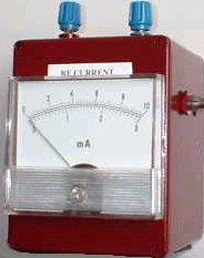
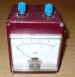
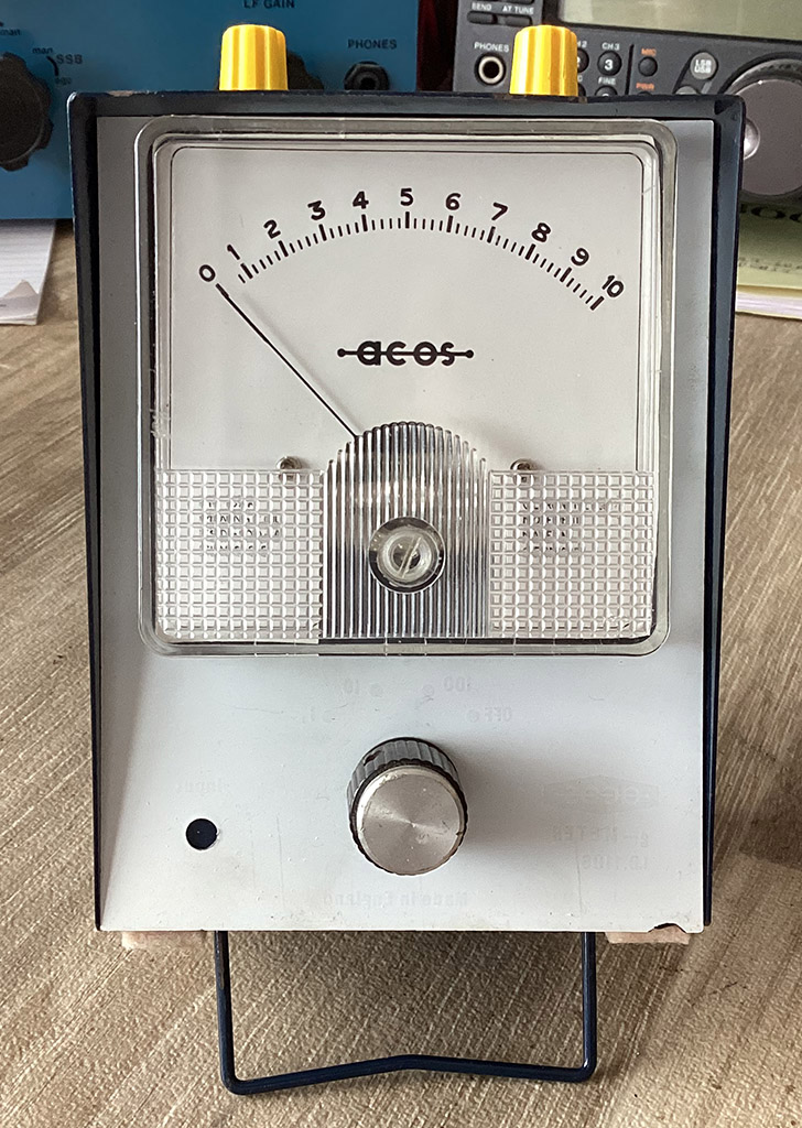
I’ve now completed a new RF ammeter. I really should have sprayed the box a nice gloss black or something to make it look mice but… maybe I will one day. This meter uses the same circuit as the meter above. The meter is 100uA FSD. The pot is 250k. The capacitor is 0.01uF. Plus a Schottky diode.
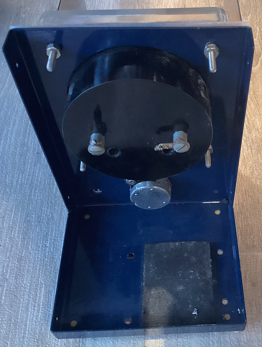
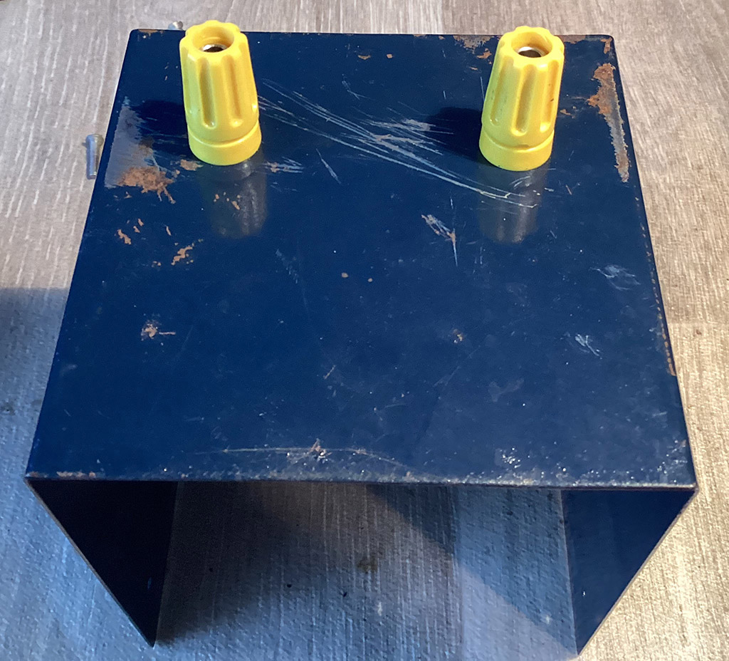
Below is the finished RF ammeter. It’s not calibrated because its main use in my shack is to ensure I have as little RF current on my top band aerial as possible. That’s sounds daft, doesn’t it? Surely, the more RF current flowing, the better?
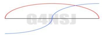
The section along a wire aerial carrying the most RF current corresponds to the point of highest radiation. For example, the high current point in a half wave aerial is in the centre. This is the part of the aerial that radiates the maximum RF signal. I aim to end-feed a half wave wire aerial. So the feed point, at the end of the wire, is the lowest current point, which is also the highest voltage point. My aerial will be voltage fed. This is why I want the RF ammeter to read very low at the feed point. Im working on an end-fed aerial at the moment.
The diagram below shows the current and voltage distribution in a half wave horizon wire. Red is current, blue is voltage.
An RF Voltmeter. See here for details.
An end-fed aerial for top band. See here for details.