An RF Volt meter, or RF sniffer, is an extremely useful piece of kit. For comparison, I’ve described an RF ammeter here. Both meters are easy and inexpensive to construct. Bear in mind that the meters are not calibrated. They are for making comparative measurements only.
When using end-fed antennas, measuring RF voltage and current can be a real help in matching the aerial to the transmitter. Put another way, they enable you to tune for maximum smoke! In the good old days before everyone had an SWR meter, before anything greater than 1:1 was thought to be dreadful, RF volt and current meters were invaluable.
A half wave end-fed antenna, that is a wire which is a half wavelength long on the operating frequency, will be voltage fed. The feed impedance will be very high. A quarter wave end-fed antenna will be current fed. The feed impedance will be very low. Placing an RF current meter in series with the end-fed wire will enable you to tune for maximum current. Standing an RF voltmeter a short distance away from the wire will allow you to tune for maximum voltage.
When the wire is a half wavelength on the operating frequency, there will be minimum current and maximum voltage shown on the meters. When the wire is a quarter wavelength on the operating frequency, there will be maximum current and minimum voltage shown on the meters. I’ll come to the point of all this later.
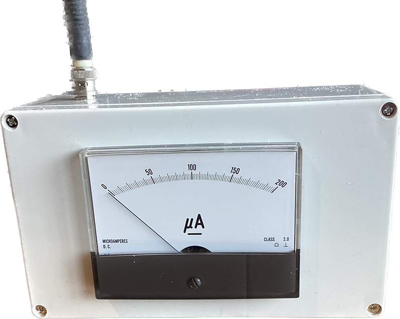
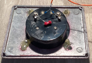
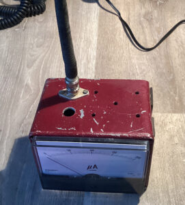
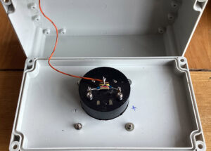
Below is my RF Volt meter. Ive mounted the meter on an old dicast box. The terminal on the side is (was) for the wire sensing antenna. I’ll be adding a decent antenna at some stage. I couldn’t use nuts and washers to mount the meter as someone has ruined the threads. Hot glue gun to the rescue! I’ve now fitted a BNC socket to the box of many holes! The rubber duck sensing antenna works very well.
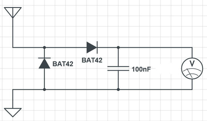
Components:
Schottky diodes. BAT42 small signal. 200mA. 30V.
Meter. Anything between 50uA and 500uA DC.
Capacitor. I’ve used a 250pF ceramic but anything up to 0.1uF will do.
The Circuit:
This little unit works so well and is so useful that I’ve ordered a decent ABS box to house it. I’ll also be adding a sensitivity control so… watch this space…
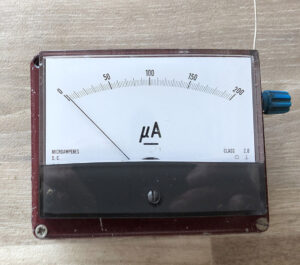
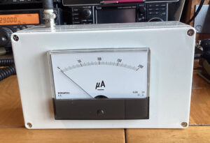
The new and improved model:
The box has arrived! I like the idea of a large meter, 4 inches by 5 inches, so I can see it from a distance. As it’s a plastic box, there’s nowhere for the ground or earth side of the meter to connect to. But it works extremely well. I’ve fitted a BNC socket for the aerial connection so anything from a rubber duck to a length of wire can be used. I’ll probably fit a sensitivity control at some stage so pop back now and then and take a look.
What use is it?
You may well be asking what the voltmeter can be used for. First of all, I think it’s educational. It’s interesting to see the meter rise when close to the feed point of a voltage fed antenna. When current fed, the meter reading will be considerably lower. Used in conjunction with an RF ammeter, you’ll be able to see exactly what’s going on. If you have an HF antenna in the garden, place the meter near to metal objects outside, and you’ll probably get a reading when transmitting. For example, a metal drainpipe could be picking up and re-radiating RF. This will show on the meter.
