Update 13/2/26:
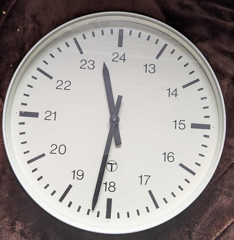
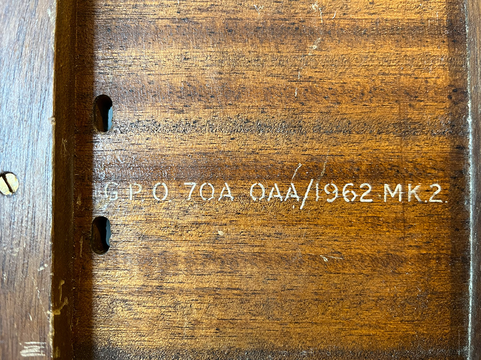
Im now the proud owner of two slave clocks, the 96A on the left and 70A on the right. Thanks, Jonathan. Both are electrical pulse types. These will be run from my Gents GPO Master Clock number 36. As you can see, the 96a 24 hour dial clock has the BT logo which was used between 1980 and 1991. I’m pretty sure the 70A was produced from around 1957.
-
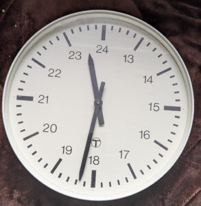
- Clock 96A
-

- Clock 70A
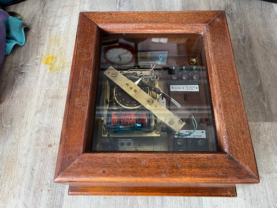
Clock 70a:
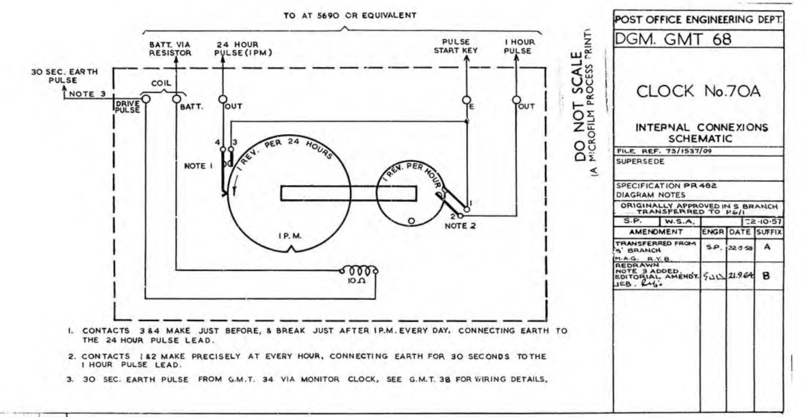
The 70A clock was designed to transmit a 30 second duration pulse at every hour and a derived pulse once every 24 hours. The 24-hour pulse is controlled in duration by an external relay-set which is operated by the 1 hour pulse.
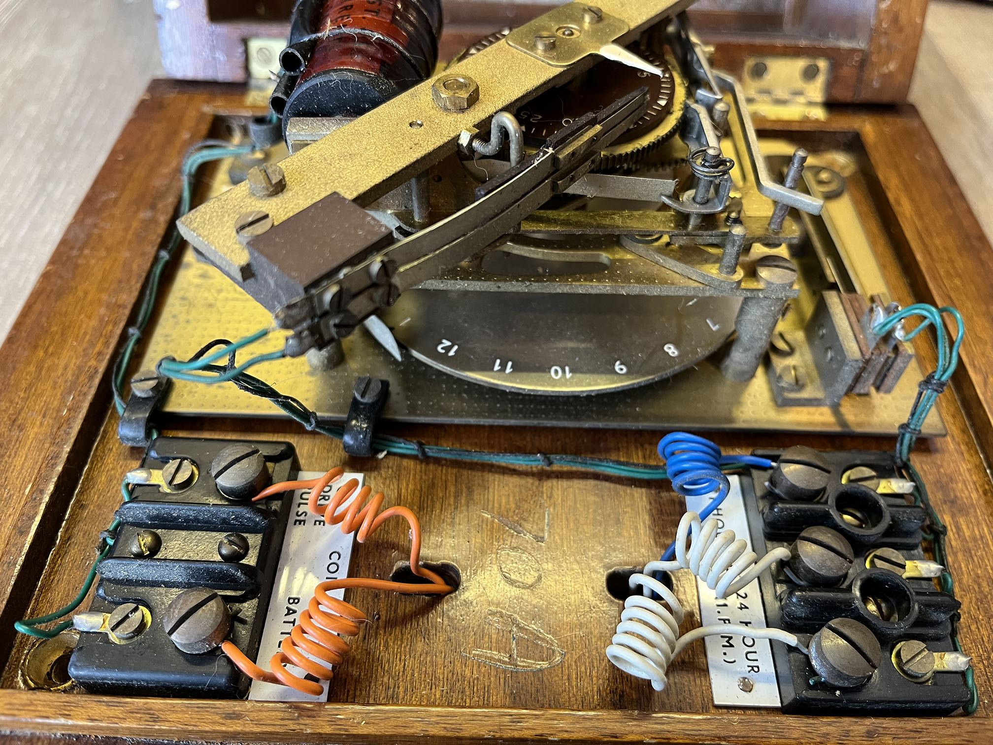
The 24 hour pulse is transmitted via springs which close a few minutes before 1 pm and open a few minutes after 1 pm. The hourly pulses and the 24 hour pulse are transmitted on separate outlets from the clock. The clock was designed for use where routiner docket control equipment, subscriber trunk dialing meter-pulse generating equipment, or disputed accounts equipment is installed. The clock is driven by 30 second pulses derived from the Master Clock Number 36.
Wiring diagram.

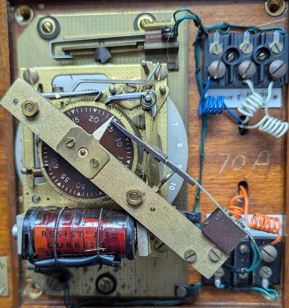
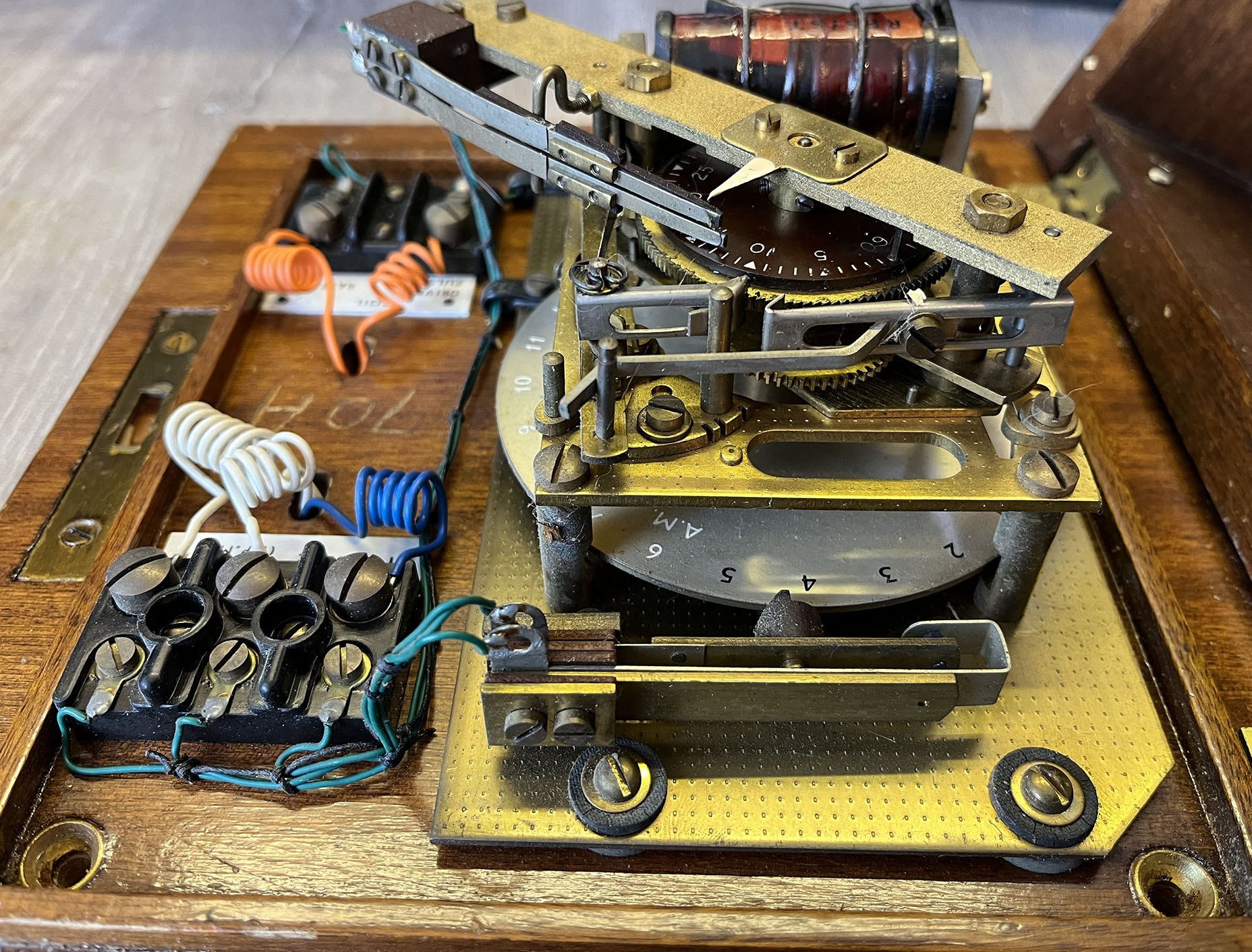
Below are a few photos of the beautifully built 70A mechanism.
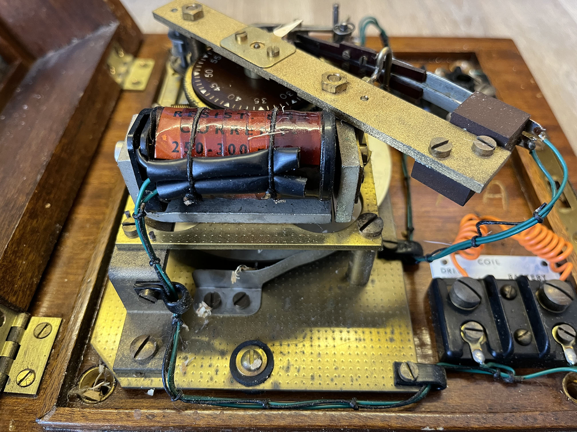
Shunt resistors:
Some slave clocks are fitted with a shunt resistor across the solenoid coil. When the pulse ends, the coil’s magnetic field collapses. This produces what is known as back EMF. This high voltage emitted by the coil can cause problems. The shunt resistor provides a discharge path which reduces arcing and contact wear in the master clock. For example, the shunt resistor fitted to clock 70A is 47 ohms. A diode across the solenoid is a better option but perhaps suitable types weren’t available back then. The 70A solenoid requires a current of 250mA to operate properly.
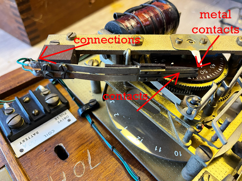
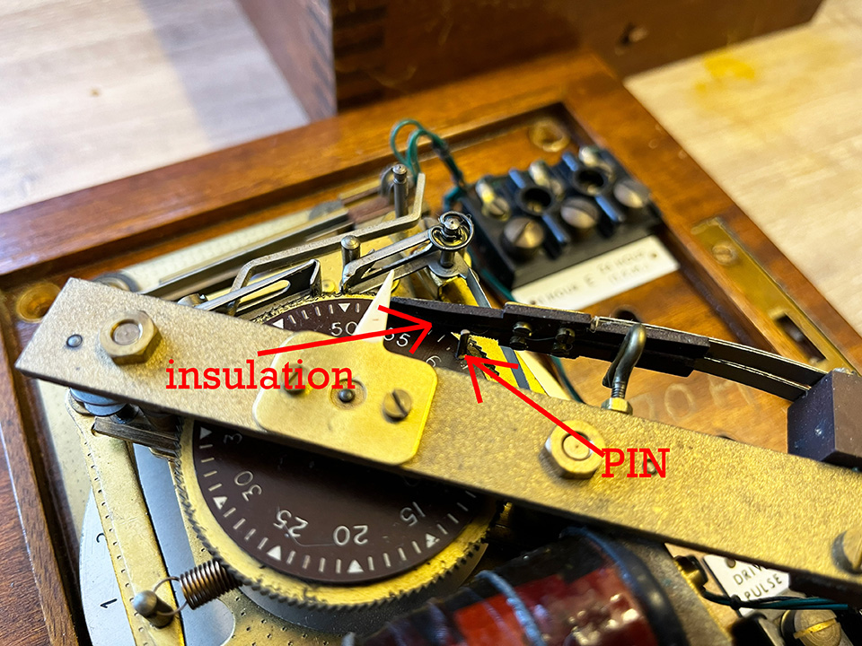
One hour pulse:
The two metal contacts, which close every hour for 30 seconds, appear to be covered by black insulating pads. The idea is that the disc revolves and the metal pin raises the two contact strips and completes the circuit. But, the metal strips are insulated so, how could it work? I couldn’t see the very small contacts at the ends of the springs strips. Thanks Jonathan for enlightening me. I need new glasses!
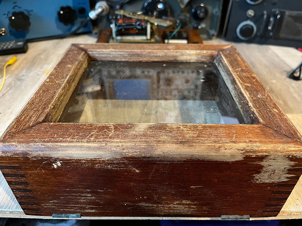
Restoring the case:
Left photo. Sanding down rough clock case. Centre photo. After wood staining and polishing. Right photo. Rear of case showing information.
GPO Slave Clock 70A video:
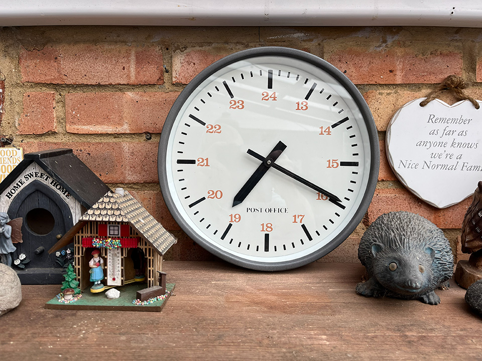
Clock 96A:
This clock runs from the master clock number 36, which transmits a pulse every 30 seconds. The clock’s solenoid should be run at 300mA. This can be set for a range of voltages by using a suitable series resistor. The clock is now installed and running on 24 volts with a higher value resistor. The solenoid current is 200mA, which seems to be fine. I’d rather under run the solenoid if possible. The pendulum adjustment is way out. the clock is losing a minute every couple of hours. It may take some fiddling to find the correct adjustment.
Update 13/3/26:
I now have a second 96A clock installed on the patio wall. I believe this clock is older than my first one as it’s marked, Post Office, rather than BT. I saw it on eBay and couldn’t resist it. How many more slave clocks will I add to the setup?