Wave traps.
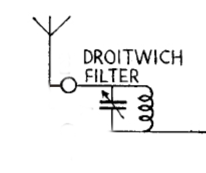
Many vintage valve radios employ a wave trap, also known as a rejector circuit. A wave trap can be invaluable where there is a strong signal from a local radio station. For example, the power of the 200kHz long wave transmitter located at Droitwich was increased during the 1930s. Anyone living close to the transmitter would have had their radio swamped by the massive signal. The answer was to fit a so-called Droitwich Filter in series with the aerial. This tuned circuit was resonant on 200kHz, so it allowed all signals through to the radio except the Droitwich signal.
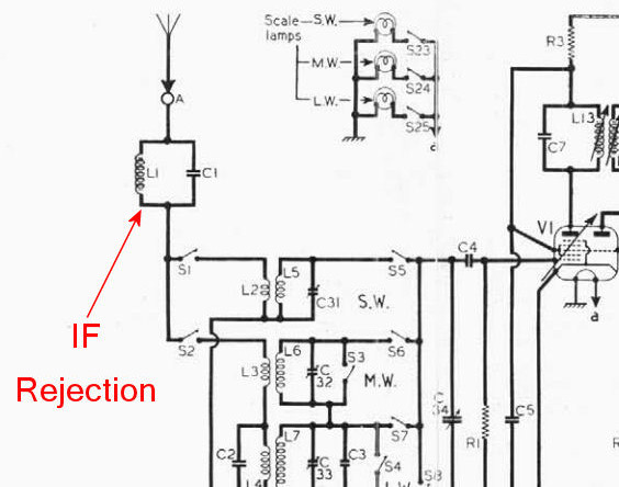
Another use for a wave trap was to help prevent IF breakthrough. Marine Morse code signals occupied the band between 200kHz and 500kHz. If the IF frequency of your radio was 465kHz, you might suffer from strong signals breaking through on your intermediate frequency from a nearby coastal radio station. By tuning a wave trap or rejector circuit to the IF frequency of the radio, any signals on 465kHz picked up by the aerial would be greatly attenuated.
The diagram below shows an IF trap in the aerial circuit of a vintage valve radio. By changing the resonant frequency of the tuned circuit, this could be used to stop strong signals from a local radio station from entering the radio.
What’s this got to do with amateur radio? UnderstandIng tuned circuits will help with building aerial tuning or matching units, and other interesting things.
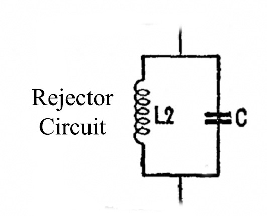
Rejector Circuit.
This is a parallel tuned circuit, shown below. This allows all frequencies to pass through the circuit except the one it’s tuned to, the resonant frequency. It blocks or rejects the resonant frequency. The parallel circuit blocks the current at its resonant frequency, where the impedance is maximum.
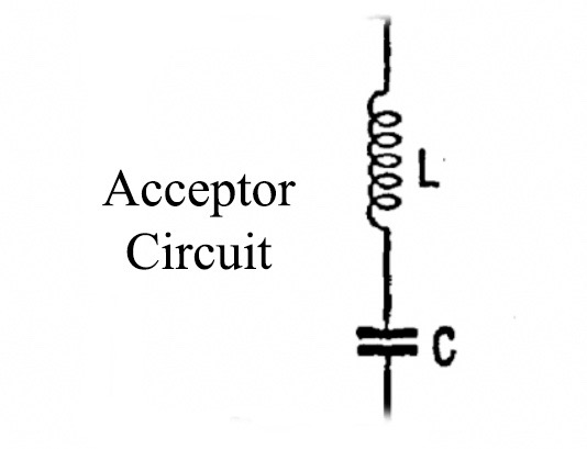
Acceptor Circuit.
This is a series tuned circuit, shown below. This blocks all frequencies except the one it’s tuned to, the resonant frequency, which it allows to pass through the circuit. The series circuit passes the current at its resonant frequency, where the impedance is at minimum.
You can see how these and similar tuned circuits are used in an aerial tuning unit here.
Current Flow.
A circuit that accepts maximum current is called acceptor circuit. A circuit that rejects maximum current is called rejector circuit.
Tuning in a radio.
You might think that you’re using an acceptor circuit when tuning your radio in to a station. The circuit will accept the frequency you want and discard all other frequencies, yes? No. This is a popular and understandable misconception. The aerial section of the variable tuning capacitor with its parallel coil is a rejector circuit. The badly drawn and very basic diagram below shows an aerial input circuit to a valve superhet radio. L1 and C1 make up the rejector circuit.
Remember that this circuit allows all frequencies to pass through except one, and that is the resonant frequency. Now, this is where the confusion comes in. The rejector will pass all frequencies down to the chassis except for the one we want, which goes straight into the control grid of the valve. The frequency we want, the radio station we want, is picked up by the aerial and goes to the grid of the valve… unaffected by the rejector circuit. The signal sees the circuit as an insulator. All other frequencies see the circuit as a short circuit down to the chassis.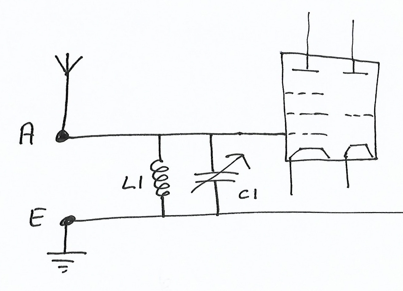
In the above circuit, C1 would be ganged (on the same shaft) with the oscillator variable capacitor. C1 will track the oscillator capacitor so it always peaks the signal on the correct part of the tuning dial. If the radio is receiving on 1548kHz then C1 will be resonant on that frequency.
I think the confusion arises because people assume that the resonant frequency, the one we want, is blocked by the rejector and doesn’t reach the valve. Think about it; yes, it is blocked by the circuit. Therefore, it can’t flow though the circuit to the chassis. The signal we want is unaffected by the circuit. Simples!