![]()
Back to the Lister D Engine page here
Contact email: [email protected]
Generating Electricity with the Lister D Engine
WARNING:
When working with car batteries remember that, although the voltage is low, the current is high. Hundreds of amps are available. That’s enough current to melt a spanner if dropped across the battery terminals. Always use fuses to protect equipment. In-line car type fuses are inexpensive and readily available. Fuse all connections to and from the battery and alternator as well as other equipment connected to the set up.
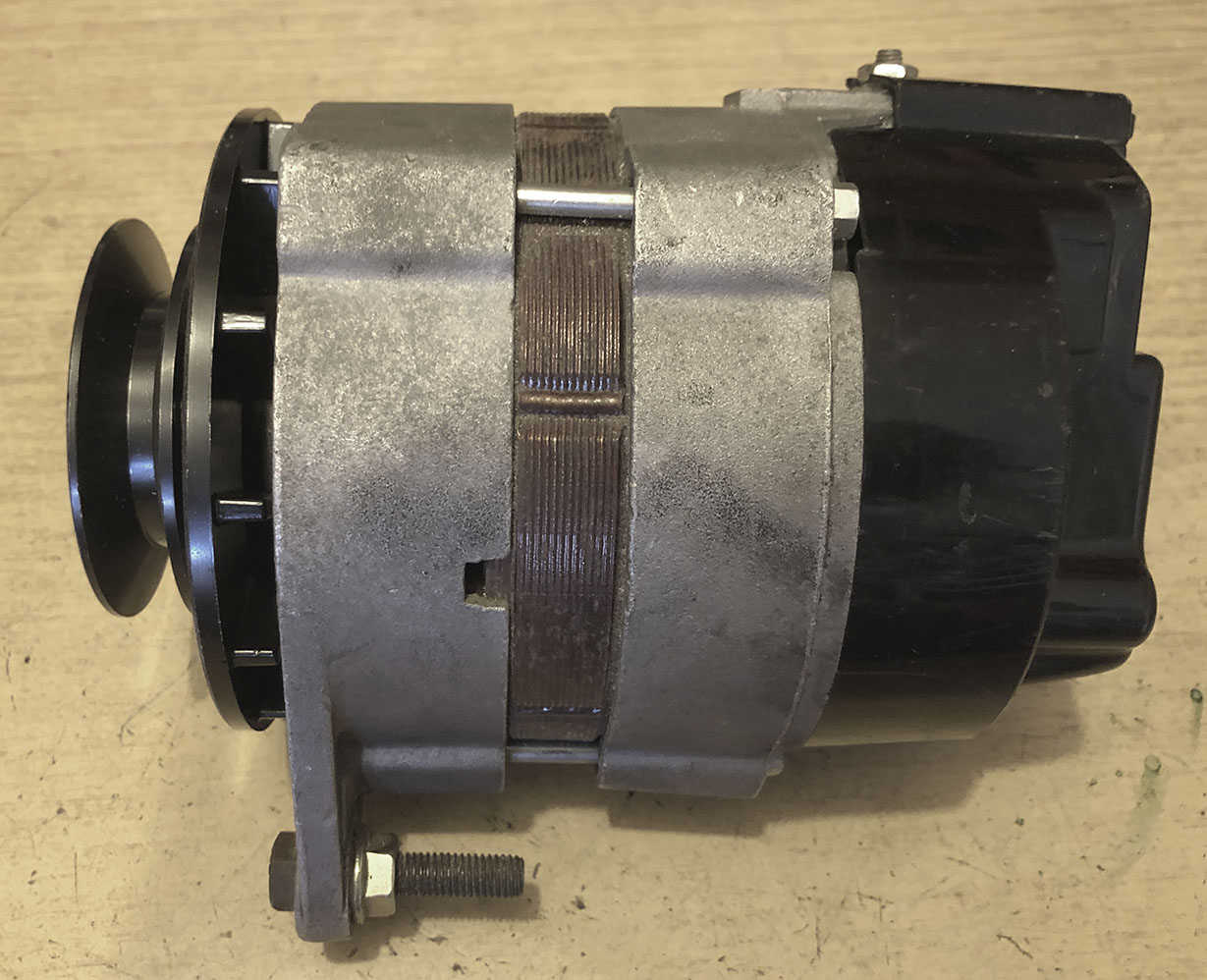
8/8/22: The alternator has arrived.
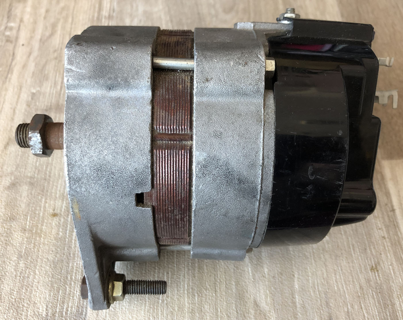
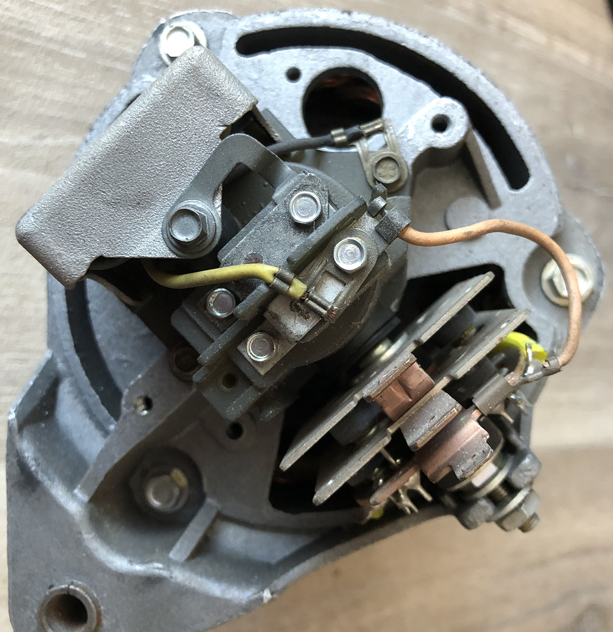
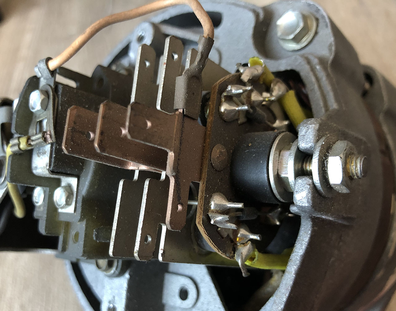
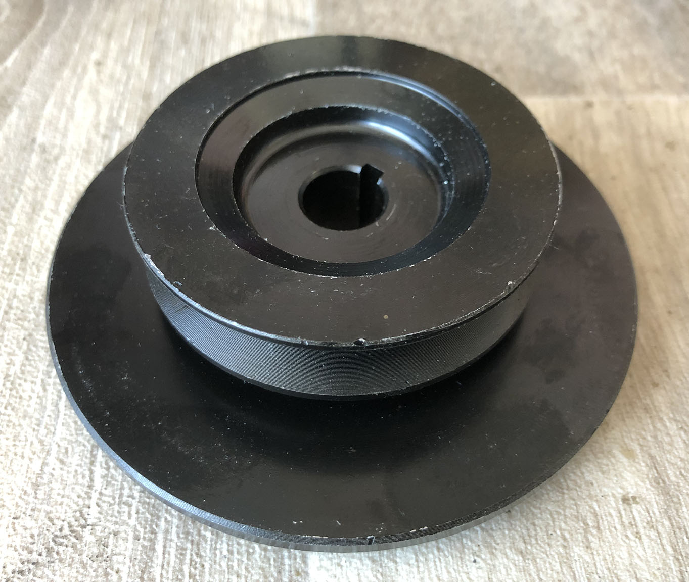
I now have a 12 Volt alternator, thanks Ron. I believe it’s a Lucas LRA 100 rated at 45 Amps, which is more than enough for my needs. Luckily, the pulley nut and woodruff key are in situ. I’ve ordered a V belt pulley with cooling fan, not the poly V type, and I’m hoping that the alternator will run fast enough to charge the battery. The idea is to make a second trolley to mount the alternator and battery. The alternator should work when running backwards as it produces AC which is then rectified. Carbon brushes run on slip rings, so they should be fine. Car alternators are AC, as the name implies, but I’ve discovered that they are three phase. The rectifier arrangement is interesting, it’s called a diode trio. More on that later… The pulley has just arrived. This replica pulley is designed to fit to an alternator which is to replace an old dynamo.
Below: Left, is the alternator. Second and third photos show the regulator and rectifier units. The pic on the right is the new V pulley.
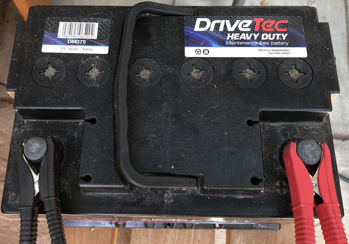
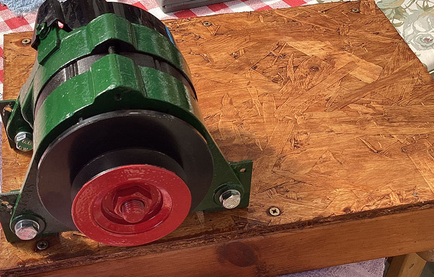
V belt pulley fitted and car battery ready to go.
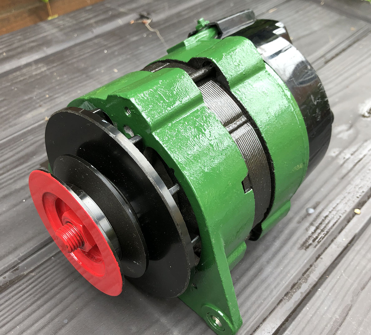
I’ve fitted the pulley to the alternator but I’m not sure which section V belt to use, A, B, C or Z. The car battery and alternator are ready to be fitted to a trolley… which I haven’t yet built! The photo on the right shows the paint job, Lister green.
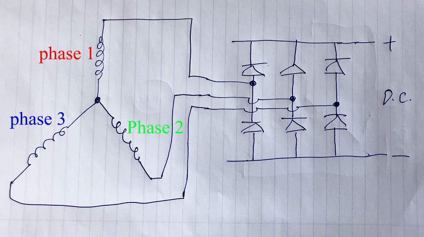
More on the three phase alternator.
In the very rough sketch below, you can see the circuit diagram of the alternator stator windings. For clarity, I’ve not shown the rotor circuit or the regulator circuit.
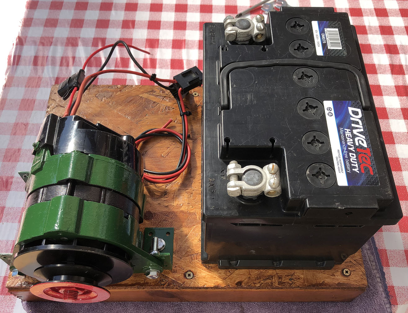
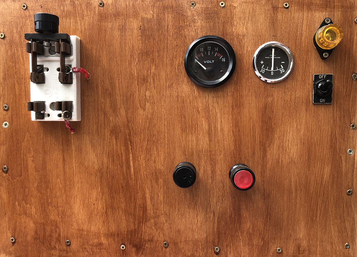
I’ve now started work on the trolley for the alternator and the 12 Volt battery. There will also be a control panel with charging indicator light, ammeter, voltmeter, knife switch etc. The photo on the right shows the trolley nearing completion.
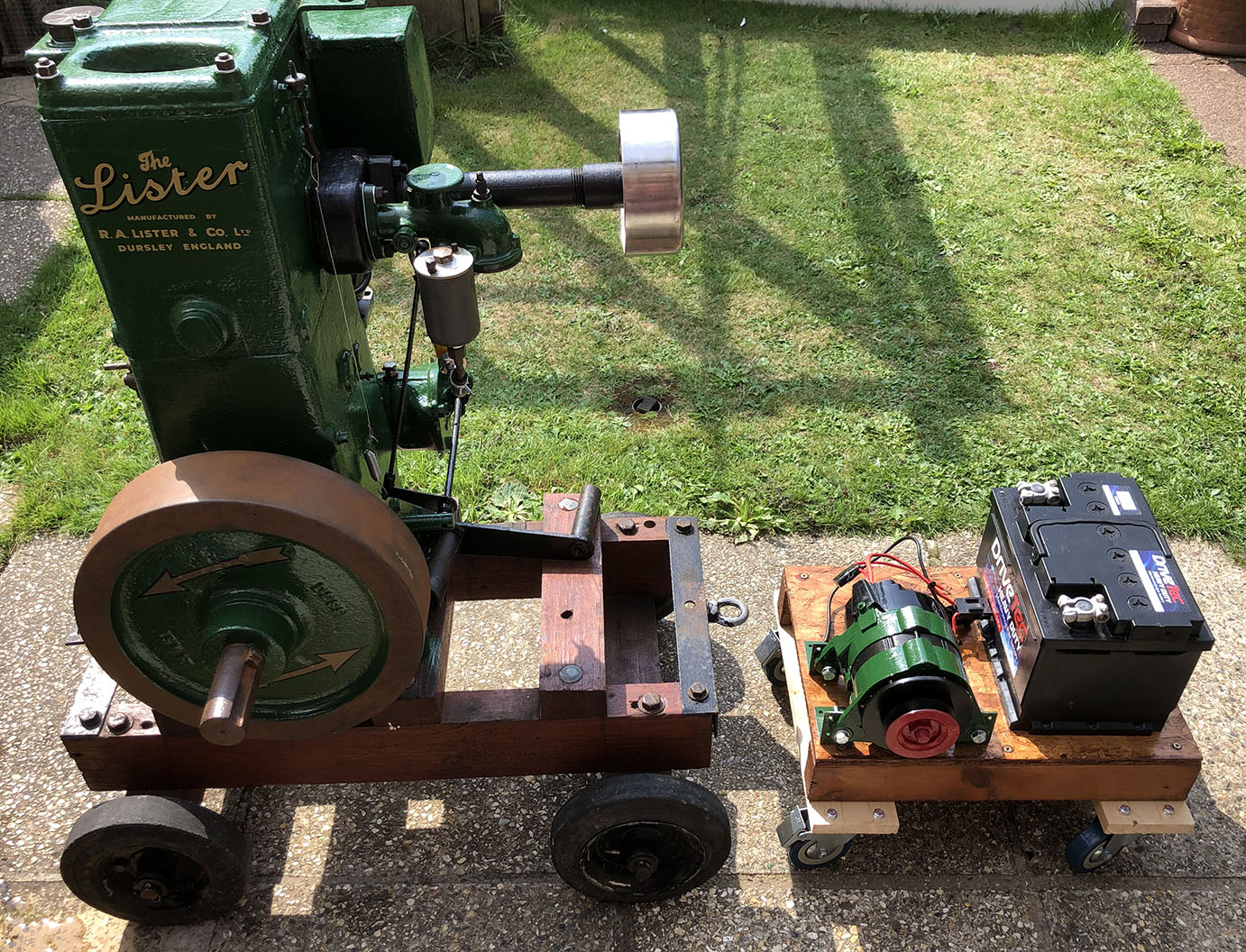
29/8/22: The generator trolley.
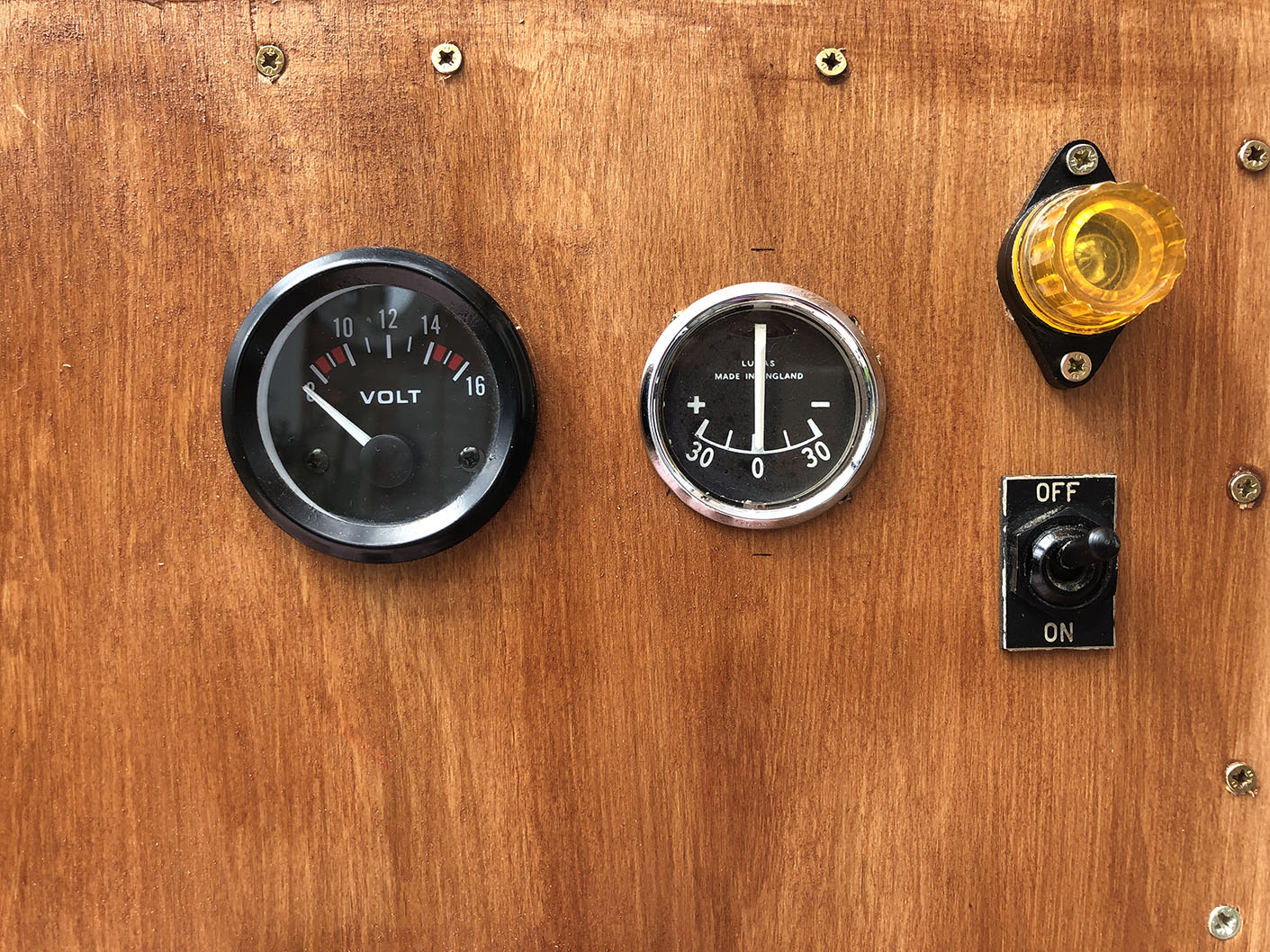
It’s coming together, at last. The indicator lamp is the equivalent to the ignition light on a car dashboard. It will go out once the alternator is charging the battery. The current flows through the bulb to excite the rotor windings and produce a magnetic field. One the alternator is generating electricity, it then becomes self-exciting and the lamp will go out.
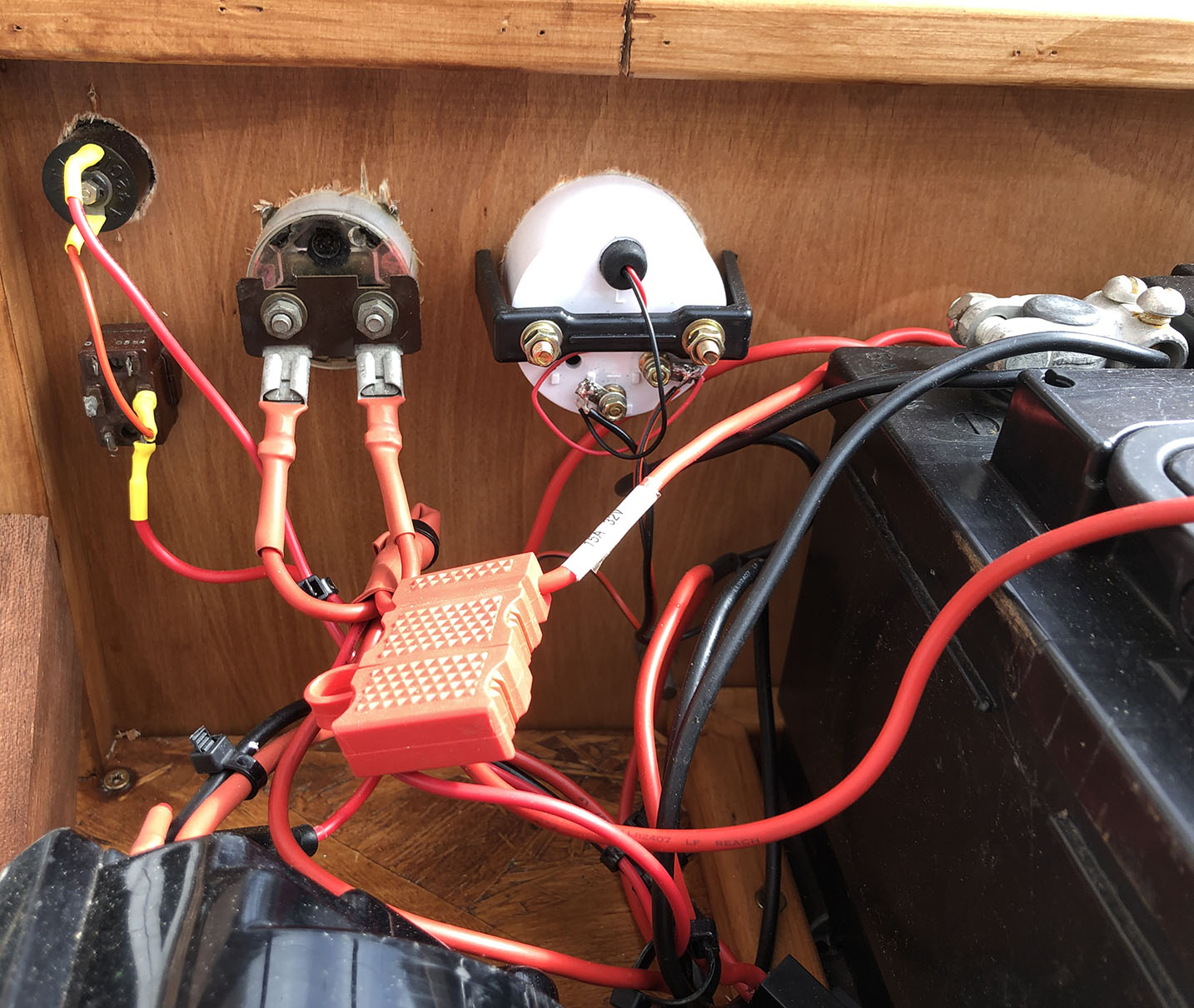
The knife switch is to disconnect the supply to the 12 Volt output terminals. I’ve fitted a voltmeter and ammeter, the vintage car type, charge and discharge 30-0-30 amps. The ‘ignition’ on/off switch is below the indicator lamp. I’ve fused the 12 Volt output terminals at 10 amps although, obviously, there’s far more current available! I think 10 amps will be enough for my needs.
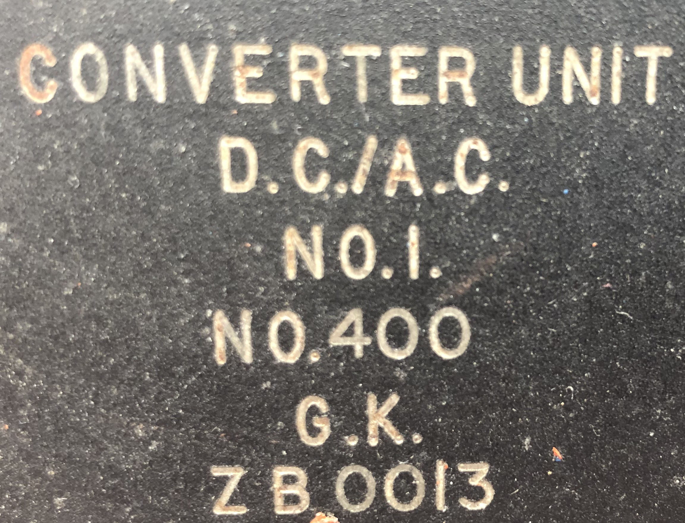
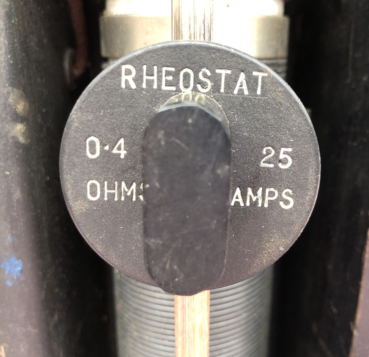
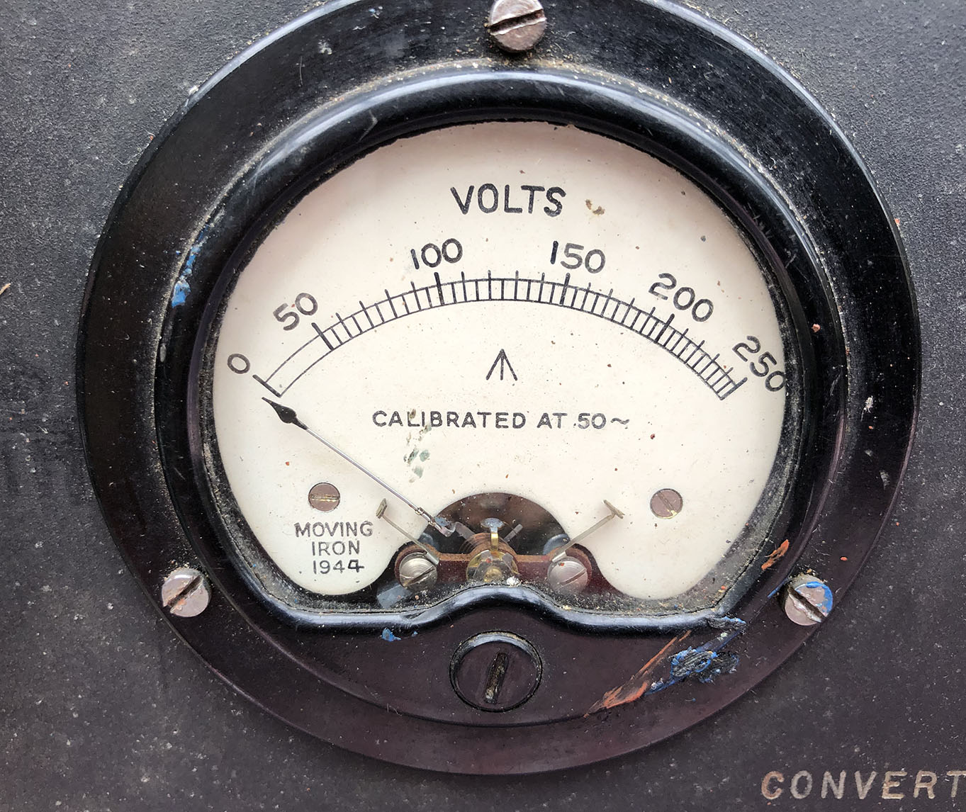
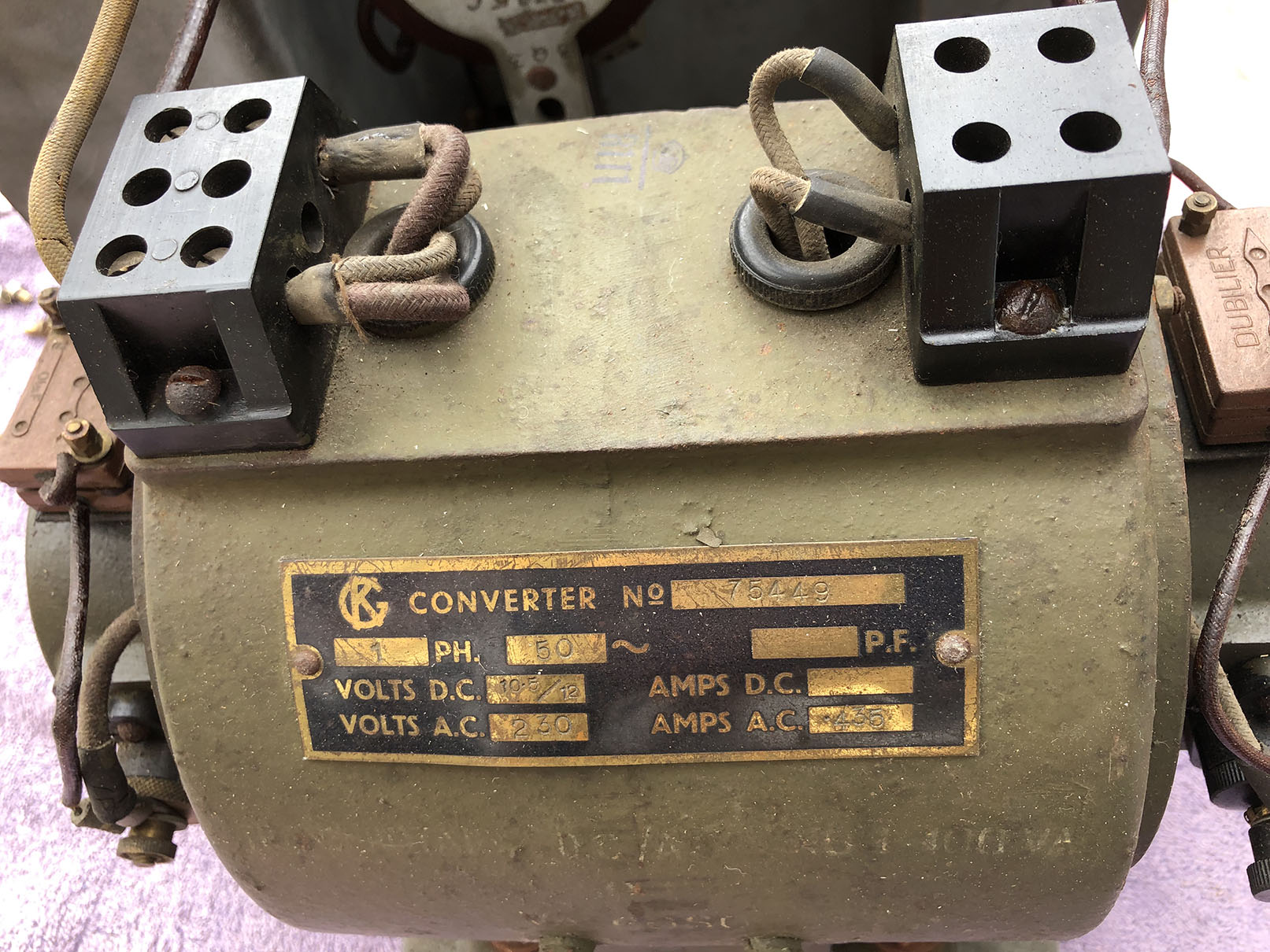
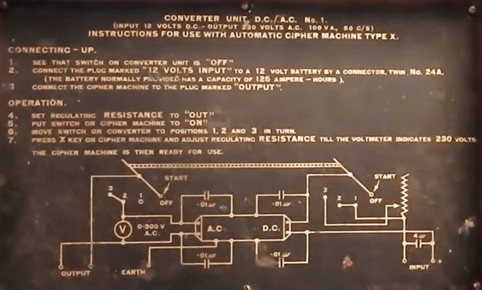
19/8/22: Converter Unit DC/AC No1.
Thanks very much to John for the converter unit, pictured below. This rotary converter was used for powering the TypeX cipher machine, where there was no mains electricity available, such as when used mobile. I can’t be sure but I believe the machine was manufactured circa mid 1940s. The date on the meter is 1944.
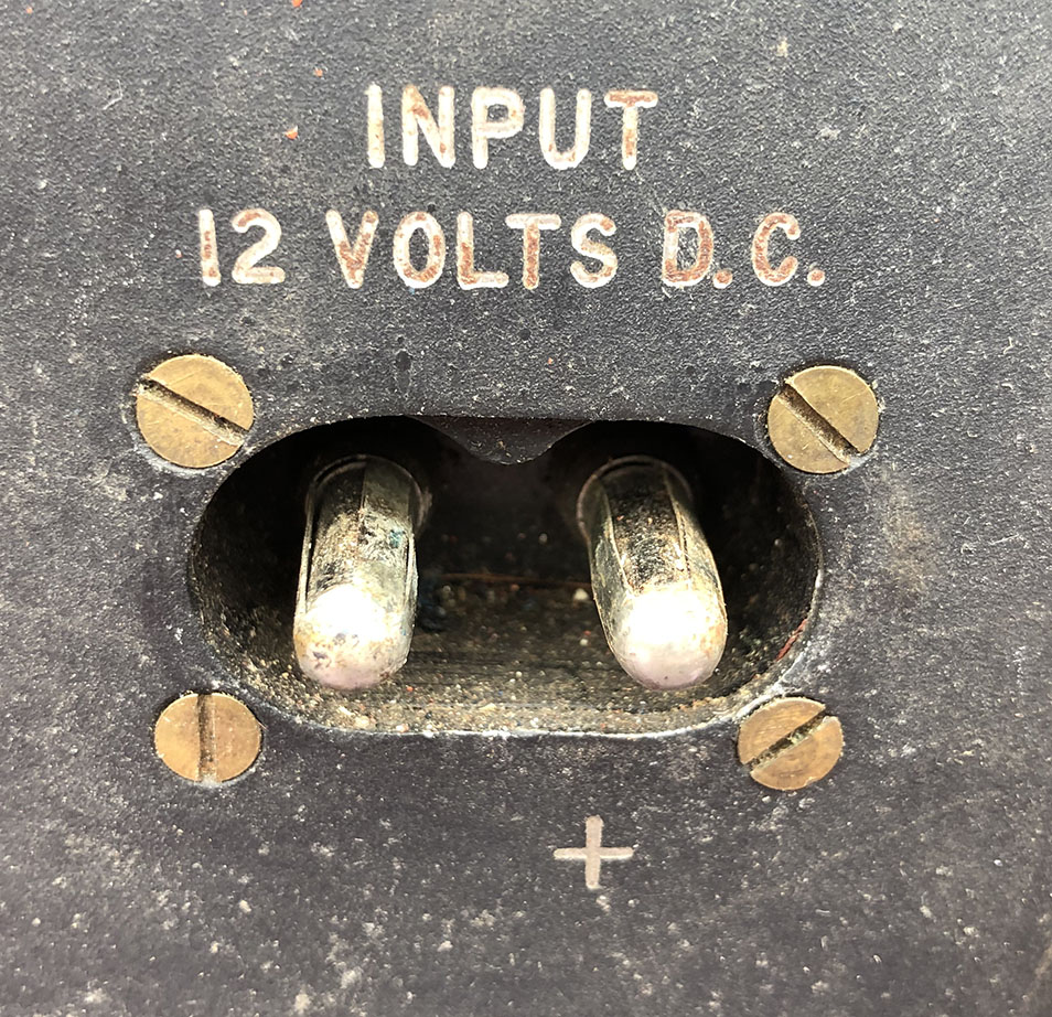
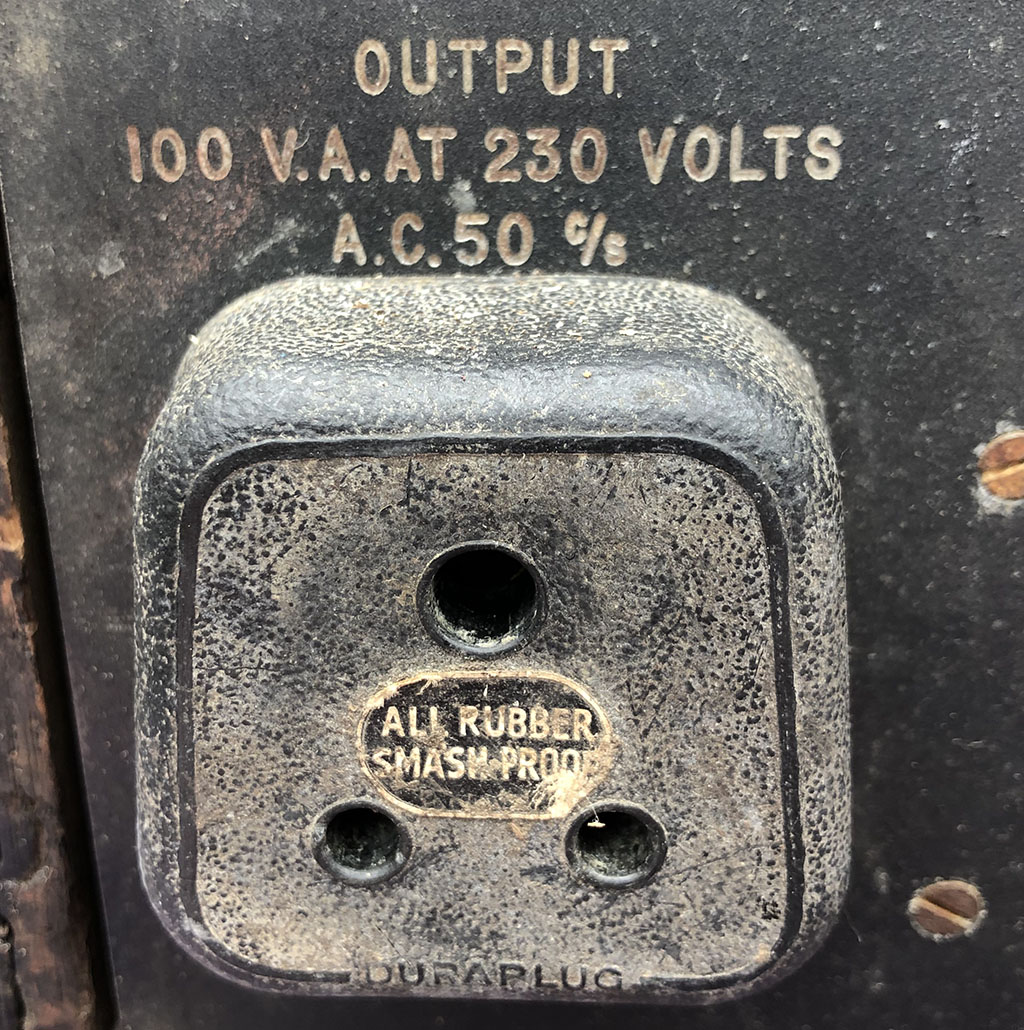
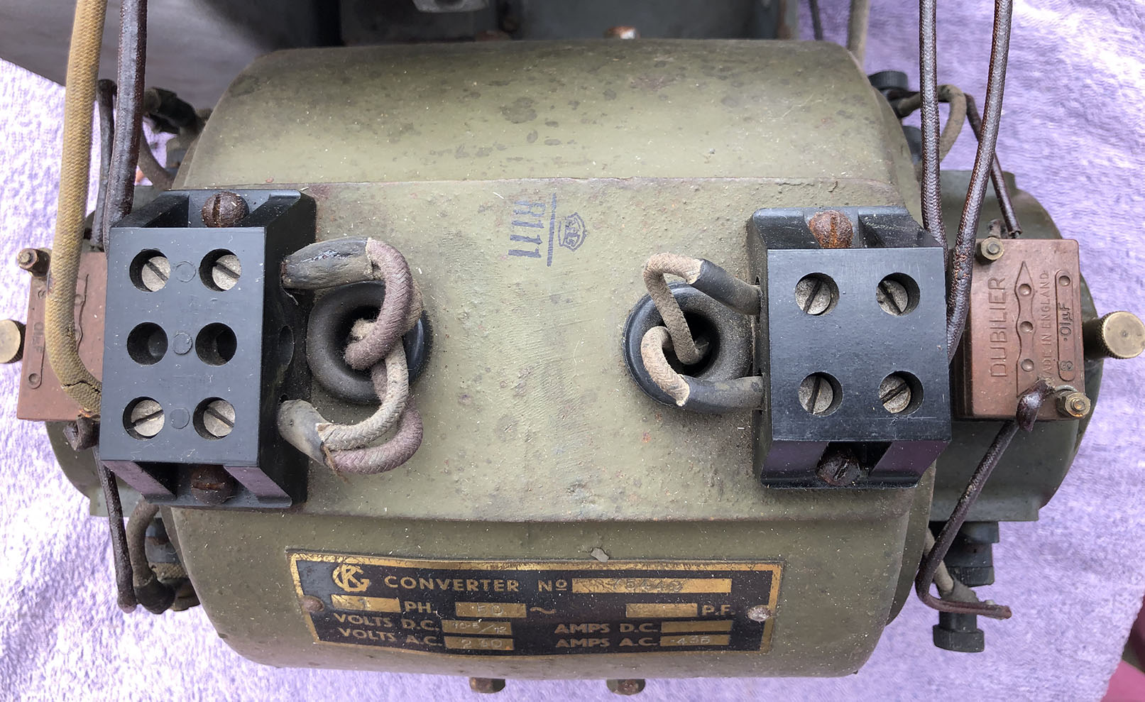
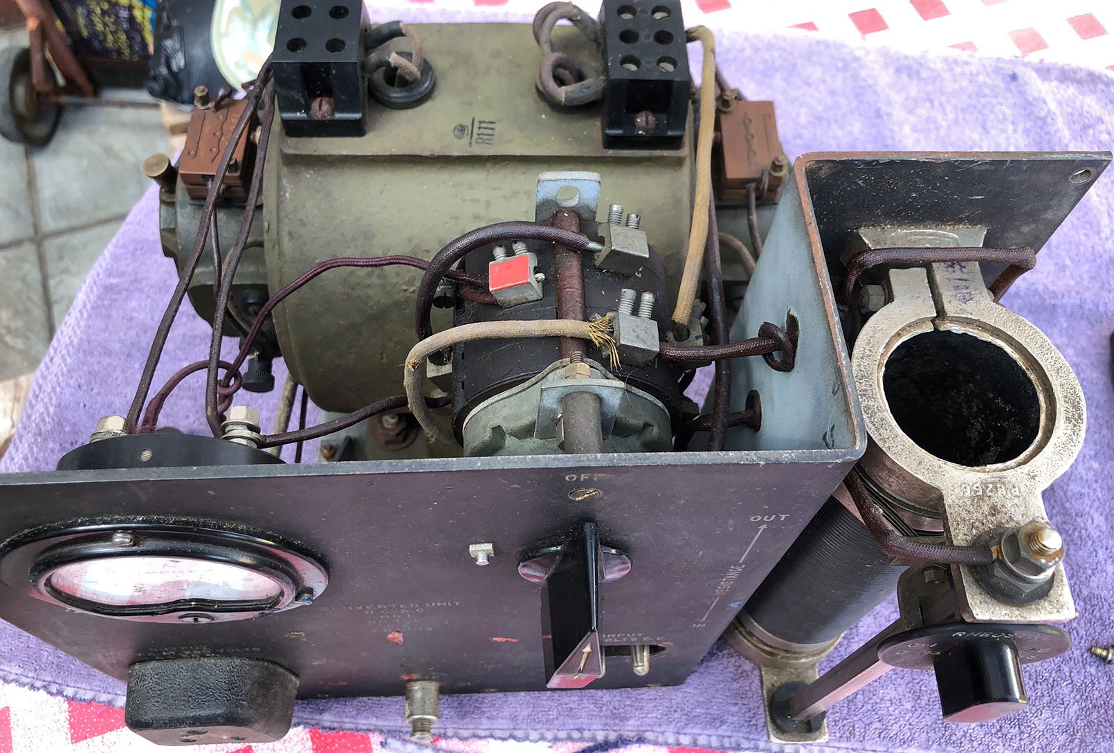
Input 12 Volts DC. Output 230 Volts, single phase 50c/s (50Hz) at 100VA. This is a rotary convertor. At one end of the shaft is a 12 Volt motor, with a commutator and carbon brushes. At the other end of the shaft is a 230 Volt single phase alternator with slip rings and carbon brushes.
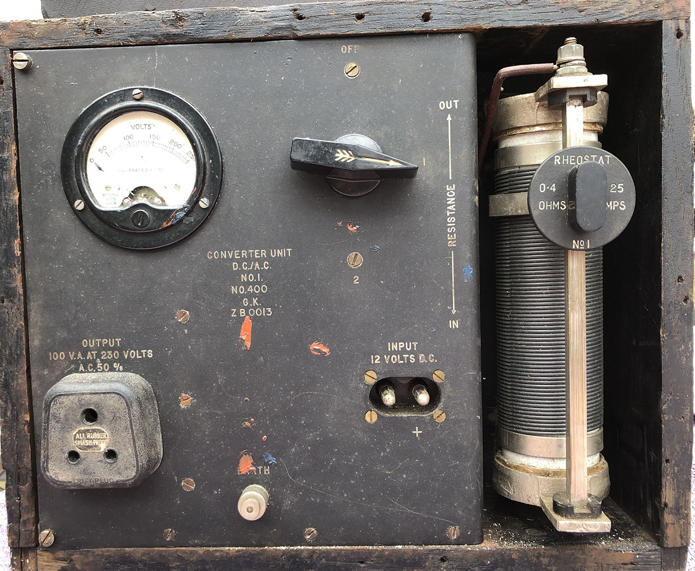
Below: Left, info plate. Centre, input. Right, output.
Below: Left, main switch and meter. Centre, rheostat knob. Right, output volt meter.
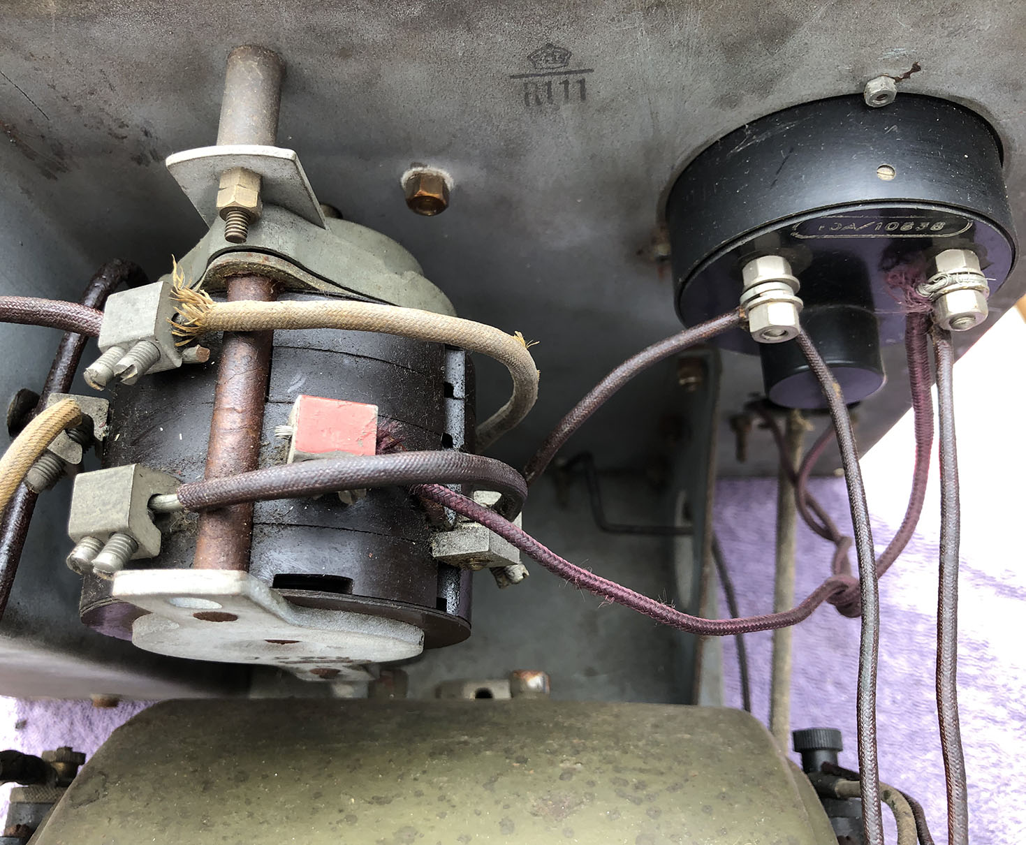
Below: Left, alternator end. Centre, motor end. Right, the converter.
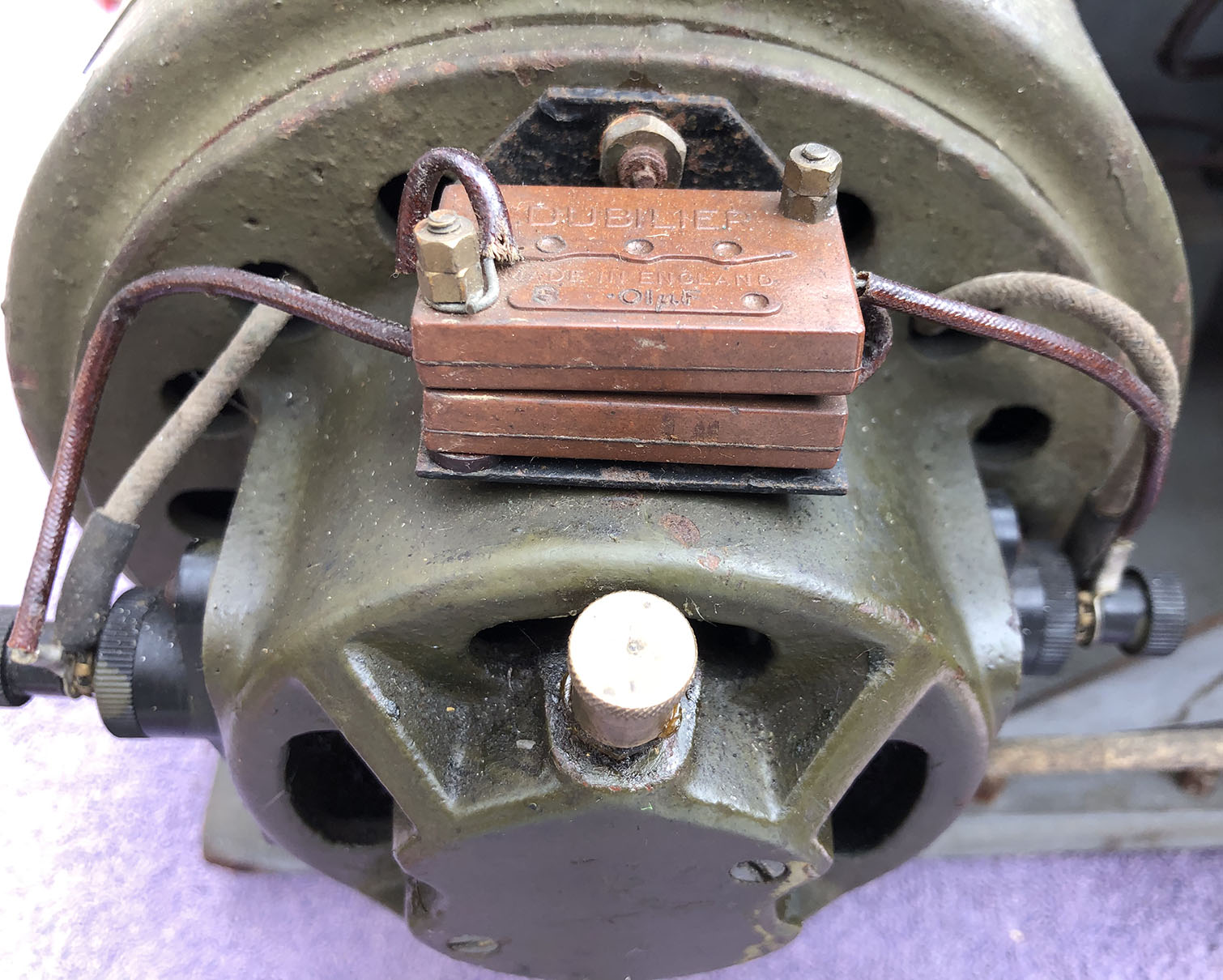
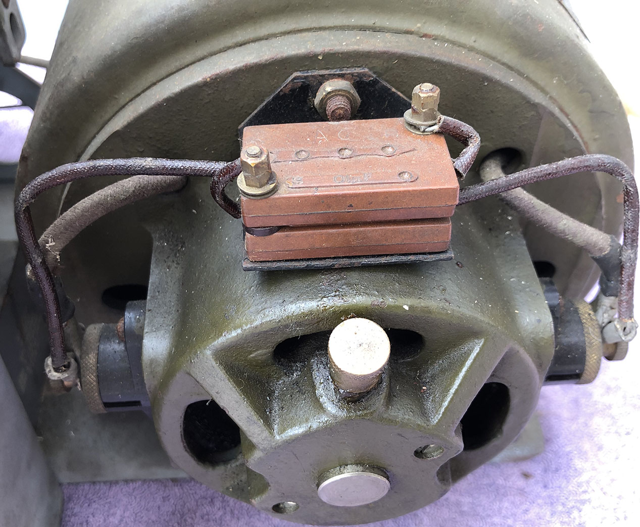
Below: Left, converter connection blocks. Centre, instructions and wiring diagram. Right, a view of the whole assembly.
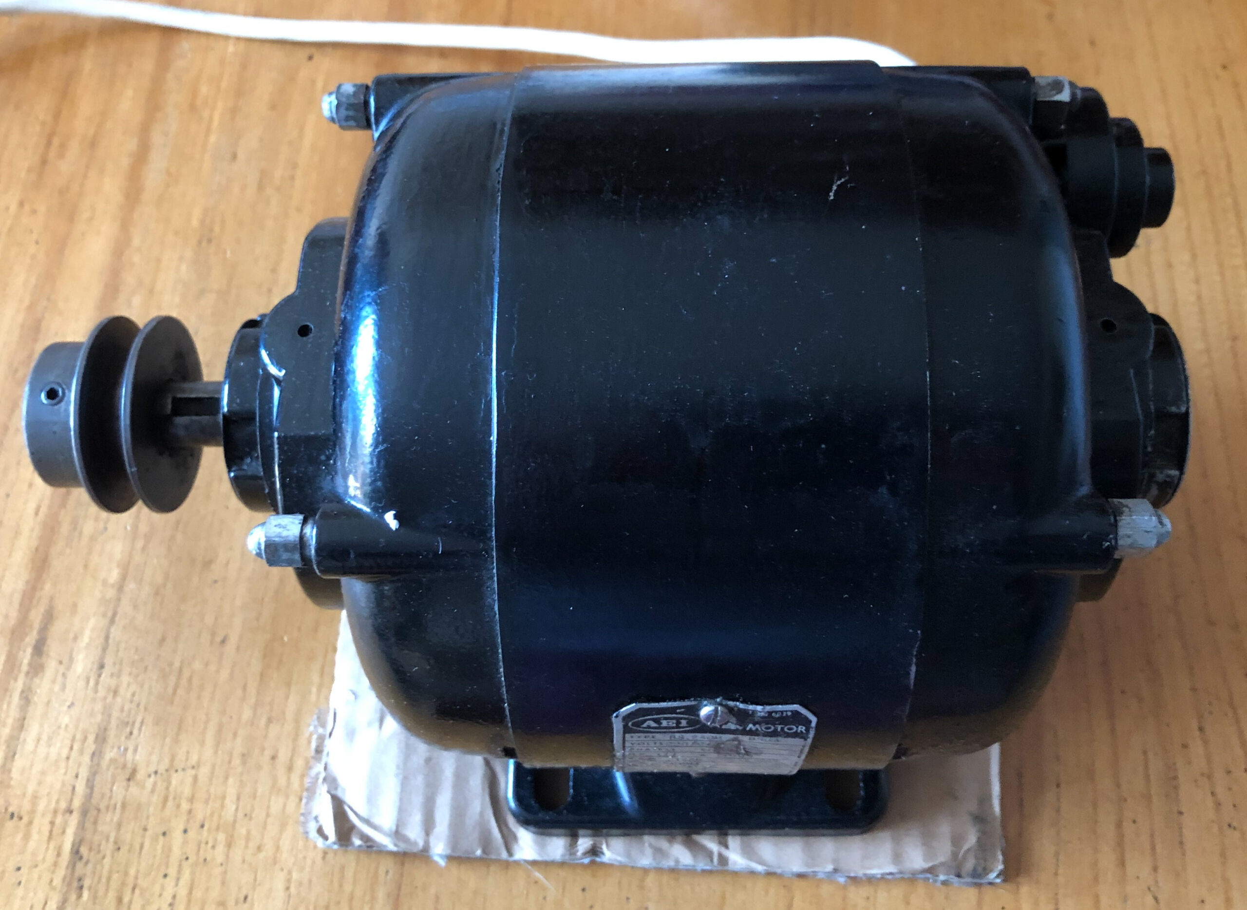
22/10/22: An induction motor.
I now have an induction motor.