I’ve just discovered that coax cable was invented by English engineer and mathematician Oliver Heaviside in 1880. Heaviside’s design was initially used for telegraphy, and it consisted of a central conductor, an insulating layer, and an outer conductor, which were all arranged concentrically. This configuration allowed for the transmission of electrical signals with minimal loss and interference, making coaxial cable more efficient than earlier forms of telegraphy cables. Coax has been around since 1880! That’s amazing!
The amount of signal loss, or attenuation, that occurs in a coax cable depends on the frequency of the signal, the length of the cable, the diameter and type of cable used. The most common cause of RF signal loss is due to the DC resistance of the coax. The resistance causes the signal to weaken as it travels through the cable, resulting in signal loss or attenuation. The higher the frequency of the signal, the greater the signal loss will be.
Another cause of signal loss in coax cable is due to the dielectric material between the inner and outer conductors of the cable. This material can absorb and dissipate the signal, causing attenuation. This is a real problem with low quality cables or those with poor dielectric materials.
It is worth noting that while some level of signal loss in coax cable is inevitable, modern cables are designed to minimize attenuation as much as possible. High quality cables can have very low signal loss, making them an excellent choice for transmitting and receiving RF signals over long distances.
For HF up to 70MHz, I use RG8X or Mini8. It’s somewhere between RG58 and RG213. For frequencies above 70MHz, I use RG213 or better. To avoid unnecessary losses, I never use coax switches above 70MHz. Rather than feed an HF dipole with coax, you could use ladder line. See here for details. Also, you might be interested in coax connectors and plugs here.
The chart below shows the approximate loss at certain frequencies for different cables at 100 feet. Please bear in mind that the figures quoted above are approximate and are for guidance only.
| 100 feet of | 30 Mhz | 50 Mhz | 100Mhz | 15o MHz | 433 MHz |
| RG-174/U | 5.5 | 6.6 | 8.8 | 10.3 | 18.1 |
| RG-58 | 2.5 | 4.10 | 5.3 | 6.1 | 10.6 |
| RG-8X | 2.00 | 2.1 | 3.00 | 4.7 | 8.6 |
| RG-213/U | 1.0 | 1.5 | 2.1 | 2.80 | 4.4 |
| RG-214/U | 1.2 | 1.6 | 1.9 | 2.4 | 5.1 |
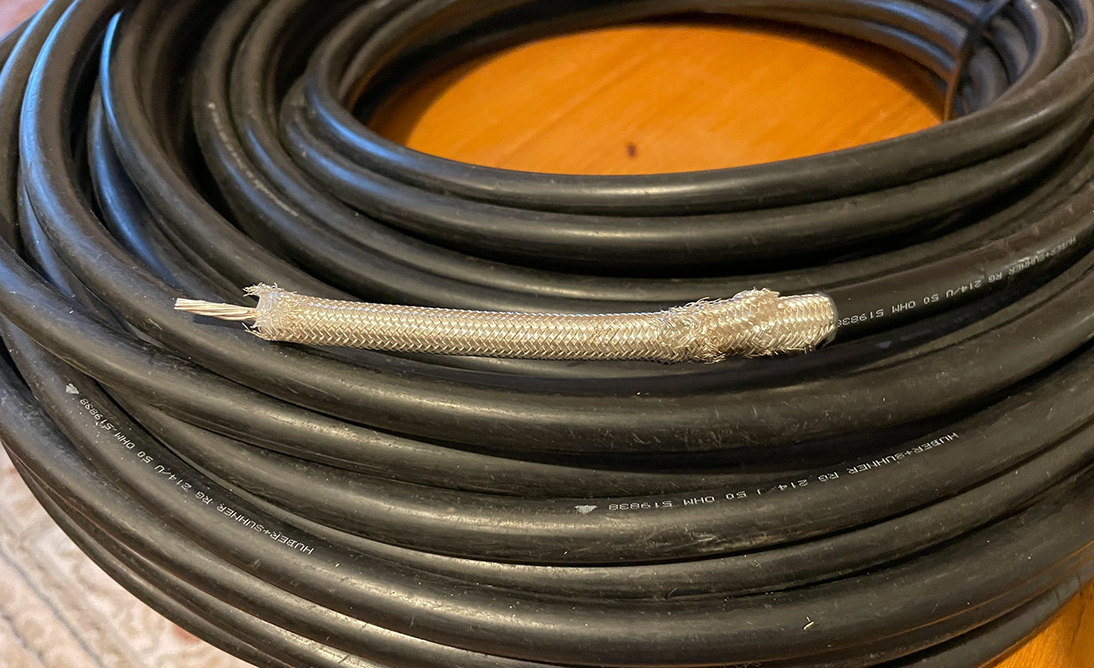
RG214/U coax:
My 4 and 6 metre aerials are fed with RG8X (mini-8) which is pretty good but each run is around 80 feet, approximately 25 metres. I’ve decided to use RG214/U instead, which should improve things. RG214/U has a double screen and both the inner and outer conductors are silver plated. As far as I can discover online, the loss per 100 feet is about the same as RG213. At higher frequencies, RG213 is less lossy than RG214. I thought this was wrong until I checked the various coax loss charts online. The photo below shows the cable thickness, it’s not easy to connect the PL259 plugs!
I’ve also used RG214 to feed my 10 metre 5/8 wave vertical antenna. The length of the coax from the radio to the antenna is 100 feet (30 metres). There’s not a great deal of loss at 28MHz but the RG214 has made a real difference.
Anatomy of coax cable:
The outer shield or braid is of vital importance. Coax can be a source of EMI, electromagnetic interference, as it can act as an antenna and radiate noise. Coax can also pick up EMI radiated from other sources such as machinery, local transmitters, nearby cables etc. See video below…
Update 24/2/24:
After a lot of work, and money, all five outside aerials are now fed with RG213 or RG214.